KY-040 Rotary Encoder breakout board part

Hello everyone,

I was searching for a Fritzing part for a KY-040 rotary encoder. They usually come on a breakout board. But I wasn’t able to find one, or rather a working one. Interestingly enough, one does find plenty Frintzing sketch images with one such part, but nowhere an actual part.

So I set out to create one myself.

KY-040_AZ_Rotary_encoder_v0.fzpz (13.8 KB)

This is the first time I created a part. Apart from encountering some weird behaviour on Fritzings part, it is working fine.

Things that I am wondering about or am unhappy with:

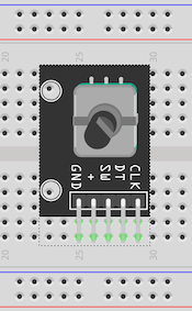
The part is created in a flat view (like lying on the table/breadboard) to scale. But it is a pretty large part, which means it is obscuring a large portion of the breadboard, which it actually doesn’t in reality. Would it be better to have a top view, and how “top” would top be. I did this part in two days from scratch, so I concentrated on the flat view and did not try a perspective view, as I would like it to be in.

KY-040_bb

Sometimes in schematic view I find that parts are pretty large compared to the rest. I can imagine why, now. It is not very easy to find a matching size for strokes and font sizes. The core parts are no help either, as the Fritzing page preaches to use inches or millimetres as SVG dimensions, but they uses pixels themselves. Neither did I find any real common standard or best practice in the many (otherwise very helpful) tutorials.
For now I think it works for me, but maybe that is an area for improvement.

Edit: I forgot one.

PCB view: What to put on the silkscreen? I now only put the space on the silkscreen, where the breakout PCB would be located. That makes it clear which way around the pads are oriented, but it also makes them look a bit floating next to it. How would the silkscreen usually look like for such breakout boards with 90° pin headers?

Feel free to use or critique.

Cheers

Welcome to the forum.

A very good first part.

If you find a sketch file (not just an image of a sketch) with a working part, the part is easy to export and reuse.

A decent breadboard view is always the hardest (for me). There are no real standards here for how ‘top’ or ‘perspective’ or ‘iso’ the view should be. It usually comes down to what image are available. When creating from scratch, it becomes personal preference plus skill and time to create an svg of what you want.

With the rotated (relative to the 90 degree headers) image you used, breadboard space can saved by connecting to the outer row of pins, and rotating (or flipping) the part to cover the power bus lines instead. For breadboard view, flipping needs to be explicitly enabled in the fzp file.

The schematic graphic is bigger than it needs to be. Pins should be 0.1 in long, and a series of them (ST, DT, CLK) should be 0.1 in apart. The pins should align (both horizontal and vertical) to the 0.1 inch grid. Your + and GND pins are not a multiple of 0.1 inch from ends of the other 3 pins, so some pins do not align to the grid.

For PCB view, the silkscreen showing the “keepout” works fine. Although, are the 90 degree headers really 0.2 inch from the top of the breakout board? Could add silk screen for the encoder shaft. Probably truncated, but enough to show that it extends over the header.

You have terminalId attributes defined in the fzp file (also) for breadboard view, but no matching ids in the svg file. The terminalId attribute is only (and only needs to be) used in the schematic. The “connector1terminal” id is missing from the rect element in the schematic file, so wires to “SW” snap to the middle of the pin, instead of the end.

FritzintCheckPart can be used to check for some technical issues. It spotted the missing and unused terminalIDs.

Thank you for your feedback!
I did raise additional questions in my head.

From what I read, I got the impression that for all three views the part dimensions should mirror the real dimensions. So would you say that this is not necessary for the schematic SVG, and that the schematic part should just be large enough to host all the pins and necessary information?

I used the real dimensions and then wanted to put the top and bottom pins in the middle, so it ends up not being a multiple of 0.1 inch from the other three pins. From how I understand your comment, I should rather have the whole part adhere to the 0.1 inch grid in the schematic SVG, as it will also move on such a grid in Fritzing’s schematic view. Hmm, but the pin’s length is 0.1 inch, isn’t it? I thought I had that right.

Yes. That is what I measured. And it also fits with standard right-angled pin headers, I found.

That sounds like a good idea.

Yes. I did not put any in the SVG after I read that they are optional and Fritzing will simply assign snap points itself. But they showed up in the .fzp file. And this is where the weird behaviour of Fritzing begins, or, at least behaviour I do not understand, yet.

Which makes me wonder, do you guys write the .fzp part files by hand, instead of using the Part Editor. I did the SVGs in Inkscape and then used the Part Editor. (To be honest, I don’t know why people keep saying that is complicated, I found that part easy. But maybe I haven’t done anything complex, yet.) What I also did, was start with an existing part (the core rotary encoder) as all tutorials I found, said, that is the only way. By now I am not convinced anymore, that that is a sane way to go.

I have the suspicion that a few irritating quirks I encountered stem from basing my “new” part on the original encoder. I may be wrong. But the terminal ids in the .fzp file may be caused by that.

So, what do you pro’s do, start from scratch and hand craft all XML files?

Doh! You are right. And there I was, thinking that I had tested my part. I guess I should have read “Part 4: Testing” of the tutorial first. I now realise I only tested the breadboard view thoroughly, not the others. My bad. Thanks for pointing that out.

I did run the FritzingCheckPart before posting. Truth be told, I mostly ignored the output. I am not too enamoured with that tool for a few reasons. But yes, it did point out the terminal ids, I just thought that the part editor might not care or even be right, so I didn’t act on it.

So all in all, I feel I should give this a second try and start the part from scratch, with more manual XML file editing.

Thanks!

Yes. Schematic is a functional/logical representation. It does not need to match the physical part. PCB view has to match the physical part, for it to fit on the board. Breadboard also need to match close to physical, but is not always the same as PCB. Sometimes breadboard is a breakout board, but the PCB is a bare component. Or breadboard is a DIP package/part, and PCB is SMD.

The + and GND pins were 0.1 inch, but the others seemed off a bit.

OK, good. It just looked too big on the schematic view. As long as it matches the part, all good.

For myself, yes (won’t really say “pro” though). But my background includes working with xml files, so I am comfortable with that. I can make choices that are hard (or even impossible) to get right with the parts editor.

Not the only way, but maybe the only ‘practical’ way for most people. Starting from something that works, and only changing the sections needed tends to be simpler than figuring out everything that is needed to get the part right working from scratch.

There is another version under development. The things it reports is the ‘best understanding’ at the time, based on user experience and research. There is no real documentation to base a lot of it on, other than directly reading the Fritzing application code, which is also very light on comments. I treat a lot of the FritzingCheckPart output like ‘lint’ output from compilers. Something that needs to be looked at, and decided on. Not as an absolute error. At lot that it complains about are errors, but not everything.

If you are comfortable editing the xml directly, the main reference is the wiki for the application repository. Part File Format

Possibly. The quality of the existing parts varies quite a lot. Or it could be a quirk of Parts Editor.

I am. I was missing a more thorough description of the SVG format, especially the use of the “gorn” attribute. But by know I think I know how that is done. So at least the schematic SVG file looks like it is easier to write in an XML editor than drawing it.

So now a XML text editor with a SVG preview would be nice. :grin:

I checked, and the terminal ids are in the original RotaryEncoder_fix.fzp for the breadboard view. So by basing the new part on it, the Parts Editor left it in the new .fzp file.

“gorn” is an inkscape specific attribute. It is not part of SVG, and Fritzing does not need it. It is just something that helps Inkscape manage some things.

What is your OS environment? I use Visual Studio Code for editing XML, including SVG directly. On linux (Fedora), eog (Eye of Gnome) displays SVG files, and does an automatic refresh when the viewed file changes. So I open the svg file in both eog and code. When I save changes in code, eog updates. For svg technical reference, I mostly use the Mozilla (MDN) web site SVG: Scalable Vector Graphics element and attribute information. Normally, specify google queries land me there.

If you want to use an xml editor to work with an svg file created with Inkscape, the source can be cleaned up a lot by first (using Inkcape), select all, ungroup multiple times, optionally group one time, save as optimized svg selecting options to tune it a bit further. That will get much closer to ‘standard’ svg, without all of the meta data that Inkscape uses, that Fritzing ignores, and is not helpful for xml editing.

I find the PCB view to also be easier to do in xml than an image editor.

This I doubt. I prepared the SVG in Inkscape (mostly using the XML editor) and did some last touch up in a text editor. There was no “gorn” in there. Then I used the Parts Editor to assign the SVG to the schematic view of the part. Saved it and checked the SVG file that Fritzing had put into the svg/user/schematic folder. And that one had “gorn” attributes added to it. So it must be something that the Parts Editor adds. In how far Fritzing makes use of it, I don’t know. It doesn’t seem to be used outside of the Parts Editor in the Fritzing code anywhere. It may rely on it in the future though.

MacOS. Yeah, you’re right, it doesn’t have to be a integrated solution, it could also be just a SVG displaying program with a watch on file changes.

My next task: update the PCB view with your earlier suggestions. I will try that.

I have added the encoder casing and encoder shaft to the silkscreen.

KY-040-AZ_v1_pcb

I am unsure if this makes it better or not. Maybe in a dashed version, to show that it is not actually touching the PCB.

KY-040-AZ_v1_pcb-dash

What I have not tried yet, is if this in any way gets problematic when the part placement on the PCB is at the border, so that the shaft silkscreen is pushed off the PCB. If that works, or makes the part not get exported in Gerber. I haven’t got a Gerber viewer for MacOS yet.

I’ll see if I find some inspiration in the KY parts from arduinomodules.info.

Curious. That does not match my experience. I have only seen the gorn attribute after working with Inkscape. But then, I do not use the Parts Editor, except when attempting to reproduce a reported problem. I build the part files (.fzpz) using zip, after creating the svg files with combinations of Inkscape and text editing, and the .fzp file with a text editor.

Fritzing does not need the gorn attribute to use a part. There are none in the parts I have created. Possibly Parts Editor uses it for something.

Yes. Here is a pointer to a couple of template files that match the graphics standard documents:

Me either and I wrote it :slight_smile: , however since all it has is the xml I can’t see a way to make it much better. If you have suggestions feel free to post them.

Peter

Thank you all for your feedback. With it, I redid the schematic and PCB views. I have created a new version of the KY-040 part. Your template, Peter, gave me some more useful pointers, too.

KY-040_AZ_Rotary_encoder_v1.fzpz (13.8 KB)

The schematic view is smaller and closer to the standard.
The PCB view includes the encoder casing and shaft on the silkscreen. Unfortunately it looks okay in Fritzing, but a dashed line seems not to translate into the gerber file, where it comes out as a solid line. I don’t know if it is not possible in the gerber format or if that is Fritzing’s fault, not anticipating something like that. So, I’m not yet convinced if that is an improvement or not.

1 Like

The new part looks good. I did not do full testing with output to Gerber, but looks good in Fritzing.

i would probably (personal preference, not a recommendation) have made the schematic even smaller, by 0.2 inch in each dimension, moving the text labels closer to the edges. “KY-040” does not really need to be part of the schematic text. If that needs to be shown, any combination of the part properties can be “turned on”, to be displayed in the part label text. In this case the “type” property. That way, the schematic image could be used (without changes) for a different rotary encoder part. Less important for a stand alone part file, but helpful for anything that gets moved into the core parts.

Ah, yes, again a good point. Even though I could image that other encoders with switch use different labels for the pins.
I’ll leave it as it is for now, but keep that in mind for future parts.
I have to get to my actual project. I am having way too much fun with the details of Fritzing parts, keeping me from my actual goal. :grin:

Yes making parts can be addictive :slight_smile: because once you know how they usually work. I can’t say the same about development …

Peter

i appreciate the part but has anyone seen a version without the faux 3d effect? im not sure why the wires connect to the ends of the wires but its making arranging the part on breadboard hard.

There probably isn’t one. This is more or less the standard way to make such parts (although I often don’t bother.) The wires connect to the end of the pins because that is where the connectors are which is again standard. You can edit the svgs to make whatever modifications you like (instructions are here although they are fairly complex

.)

Peter