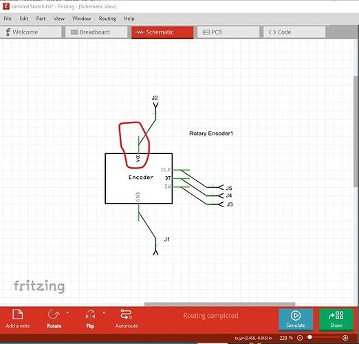
First of there is already a part for this:
which has an improved version later in the post. That said, as @roboteach said your zip file is the entire folder which is why the part won’t load. To correct that zip only the files to a .fzpz file and it will work. Doing that indicates a number of errors: schematic lacks terminalIds which causes this:
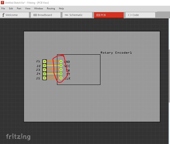
where the wire connects to the middle of the connector rather than the end as it should. As well in pcb the hole sizes are incorrect (and inconsistent):
which shows in the gerber drill.txt file like this
; NON-PLATED HOLES START AT T1
; THROUGH (PLATED) HOLES START AT T100
M48
INCH
T100C0.035870
T101C0.035871
T102C0.038000
%
T100
X009111Y012777
T101
X009111Y010777
X009110Y011777
X009111Y013777
X009111Y014777
T102
X005111Y010777
X005111Y013777
X005111Y011777
X005111Y014777
X005111Y012777
T00
M30
The top two entries
T100C0.035870
T101C0.035871
should match the third
T102C0.038000
which is the correct size for a 0.1in header. The 0.035in holes are too small. Running your part through FritzingCheckPart.py flags these errors:
Error 69: File
‘svg.breadboard.KY-040_M274_Encoder_d33e40f98d1af7a1907cc6ccb62876a1_3_breadboard.svg.bak’
At line 22
Found a drawing element before a layerId (or no layerId)
Error 69: File
‘svg.schematic.KY-040_M274_Encoder_d33e40f98d1af7a1907cc6ccb62876a1_3_schematic.svg.bak’
At line 30
Found a drawing element before a layerId (or no layerId)
Error 77: File
‘svg.schematic.KY-040_M274_Encoder_d33e40f98d1af7a1907cc6ccb62876a1_3_schematic.svg.bak’
At line 227
terminalId connector13terminal can’t be a g as it won’t work.
Error 18: File
‘part.KY-040_M274_Encoder_9c03b2867a9e0537c22532e90d8f3222_4.fzp.bak’
Connector connector8terminal is in the fzp file but not the svg file. (typo?)
svg svg.schematic.KY-040_M274_Encoder_d33e40f98d1af7a1907cc6ccb62876a1_3_schematic.svg.bak
Error 18: File
‘part.KY-040_M274_Encoder_9c03b2867a9e0537c22532e90d8f3222_4.fzp.bak’
Connector connector9terminal is in the fzp file but not the svg file. (typo?)
svg svg.schematic.KY-040_M274_Encoder_d33e40f98d1af7a1907cc6ccb62876a1_3_schematic.svg.bak
Error 18: File
‘part.KY-040_M274_Encoder_9c03b2867a9e0537c22532e90d8f3222_4.fzp.bak’
Connector connector10terminal is in the fzp file but not the svg file. (typo?)
svg svg.schematic.KY-040_M274_Encoder_d33e40f98d1af7a1907cc6ccb62876a1_3_schematic.svg.bak
Error 18: File
‘part.KY-040_M274_Encoder_9c03b2867a9e0537c22532e90d8f3222_4.fzp.bak’
Connector connector11terminal is in the fzp file but not the svg file. (typo?)
svg svg.schematic.KY-040_M274_Encoder_d33e40f98d1af7a1907cc6ccb62876a1_3_schematic.svg.bak
Error 18: File
‘part.KY-040_M274_Encoder_9c03b2867a9e0537c22532e90d8f3222_4.fzp.bak’
Connector connector12terminal is in the fzp file but not the svg file. (typo?)
svg svg.schematic.KY-040_M274_Encoder_d33e40f98d1af7a1907cc6ccb62876a1_3_schematic.svg.bak
The no layerId errors mean that your part won’t export as an image, the rest should be self explanatory. The following tutorial may help you in correcting the errors:
Part creation howto part 1 breadboard and pcb
Peter

