Hello every one.
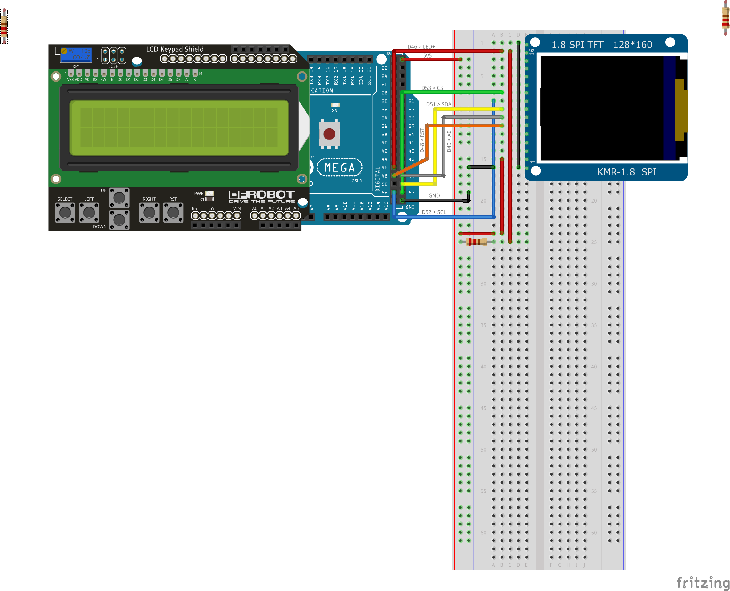
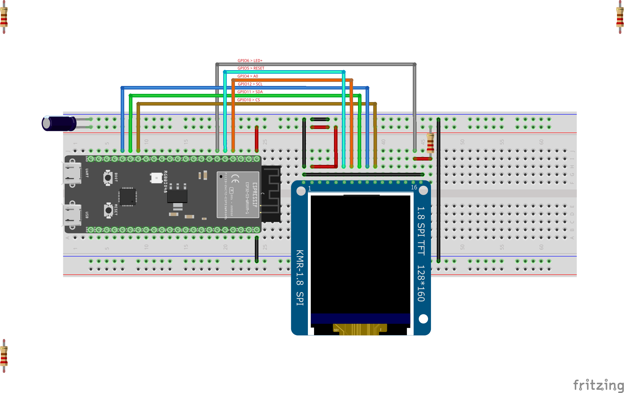
I have made a more visually accurate board graphics for the KMR 1.8 SPI and combined it with the PCB layout created by Van Epp. (@vanepp )

External Download Link:
Cheers
Hello every one.
I have made a more visually accurate board graphics for the KMR 1.8 SPI and combined it with the PCB layout created by Van Epp. (@vanepp )
External Download Link:
Cheers
The file is only a svg not a part so it doesn’t appear to be of much use.
Peter
Hello Peter.
Sorry if anything was out of the norm.
Any instructions or brief help in how to promote this to a usable part, and I will try to do so accordingly.
New to Fritz as well. As of now what I did was simply edit the graphics that was present in a fritz file that I found from your source only.
I made one to be used with my project.
I can otherwise use it to draw the board visuals. Followed the instructions as per the official guide on adding new image.
The svg you posted has no layerId (which will cause the part to not export as an image) and no connectors. You can add them via parts editor, but most people won’t know how to do that. This tutorial will give you instructions on how to make parts. but is complex (as is making parts.) That appears to have been done (how correctly is unclear without the part to run through FritzingCheckPart.py.) It would be better to post the .fzpz file of the part used in this sketch as it should be more correct (and thus more use) than the svg. If you upload the .fzpz file for the part used in the sketch I can run it through FritzingCheckPart.py and tell you how to fix any complaints.
edit
upload is 7th icon from the left in the reply menu and will accept .fzz (sketch), .fzpz (part) and .svg files (among other less common ones.)
You may have already seen these as they get posted a lot, both apply to current Fritzing versions where many of the others are for older software versions (both these are 5 or more years old now though.)
I lately learned there aren’t links to the videos in Old_Grey’s tutorial so you need to do a google search for the title and then they come up on YouTube.
Peter
Understood.
Thank you for the guidance, I believe I am halfway through the hoops, there is another half of the journey remaining though.
It was borderline stupid of me to not check that I am uploading a plain SVG file and not the fritzing file. Here is the part exported as a fritzing file. Retains your PCB designs and connections, only the graphics modified.
TFT 1.8 inch 160x128 w microSDRev2.fzpz (20.0 KB)
With gratitude
Ninaad
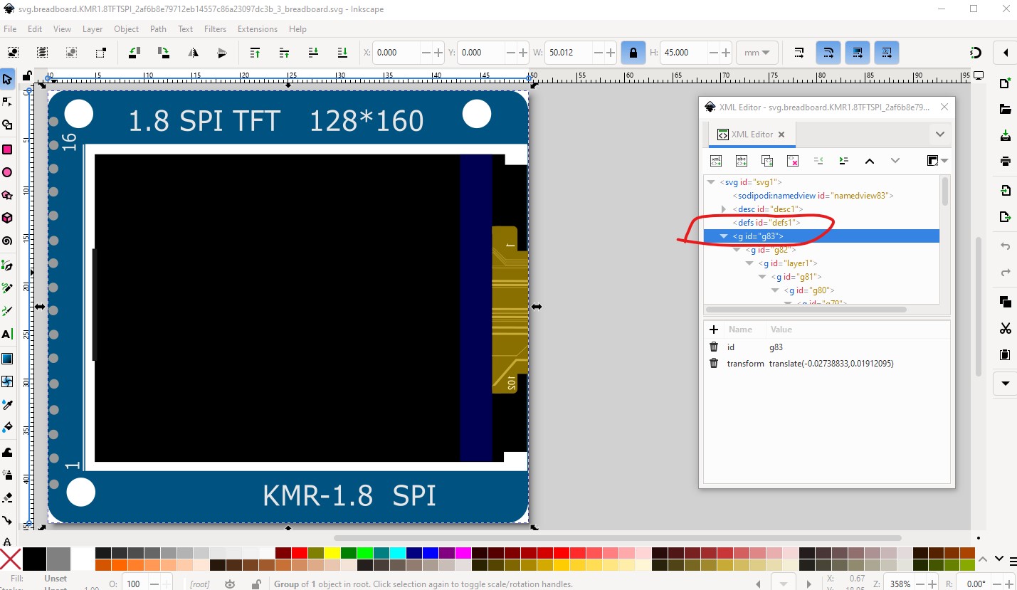
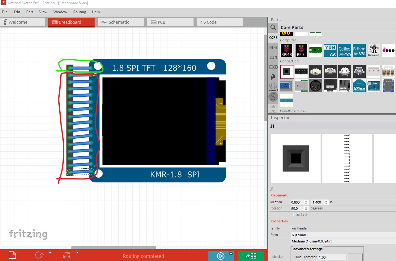
Inexperienced, not stupid, you are already in the %99 profile by even trying to make a part, very few people do. Part making is very complex and bites without warning it usually takes about a year or more of making parts to become good at it. At that the only thing FritzingCheckPart.py produced an error on is the lack of a breadboard layerId (which as noted earlier only prevents the part being exported as an image.) That isn’t the only mistake but the only one FritzingCheckPart.py was capable of finding. Here is the fix for the layerId:
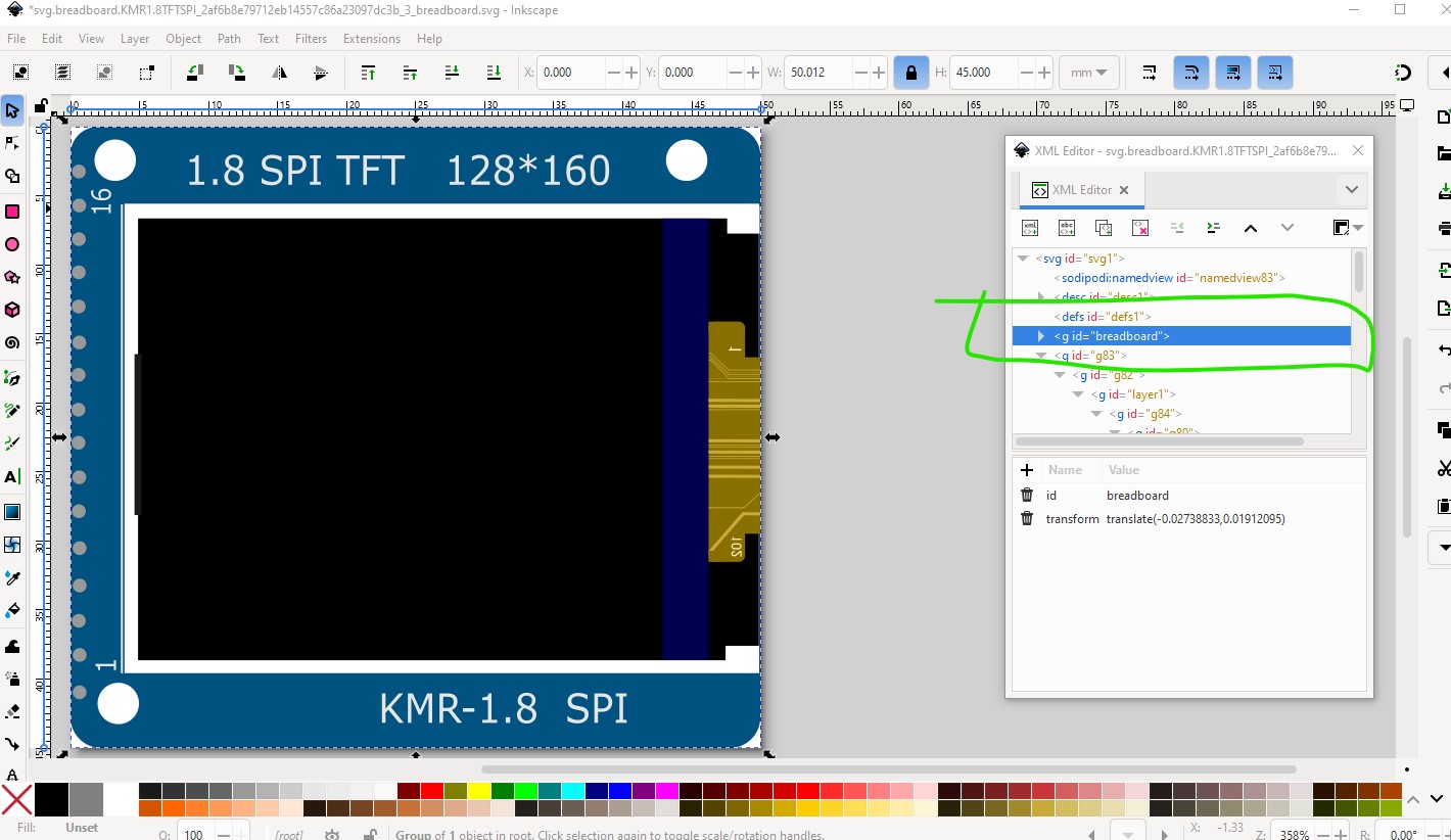
This group id needs to be breadboard to match the layerId in the .fzp file like this:
The other mistake is that the connectors are not on 0.1in boundaries in breadboard. FritzingCheckPart.py doesn’t currently check for that (it could, but it usually isn’t an issue.) That causes this:
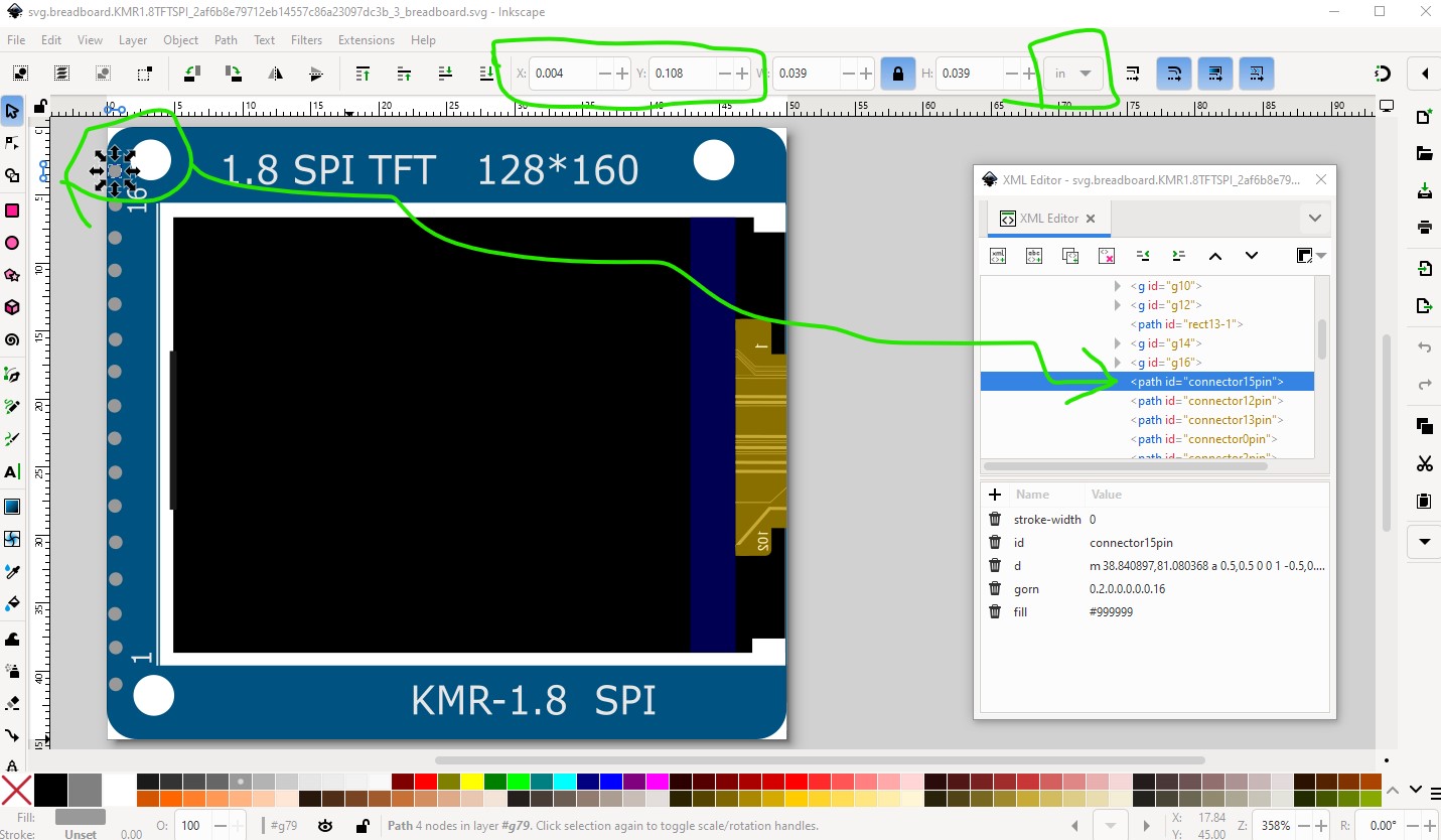
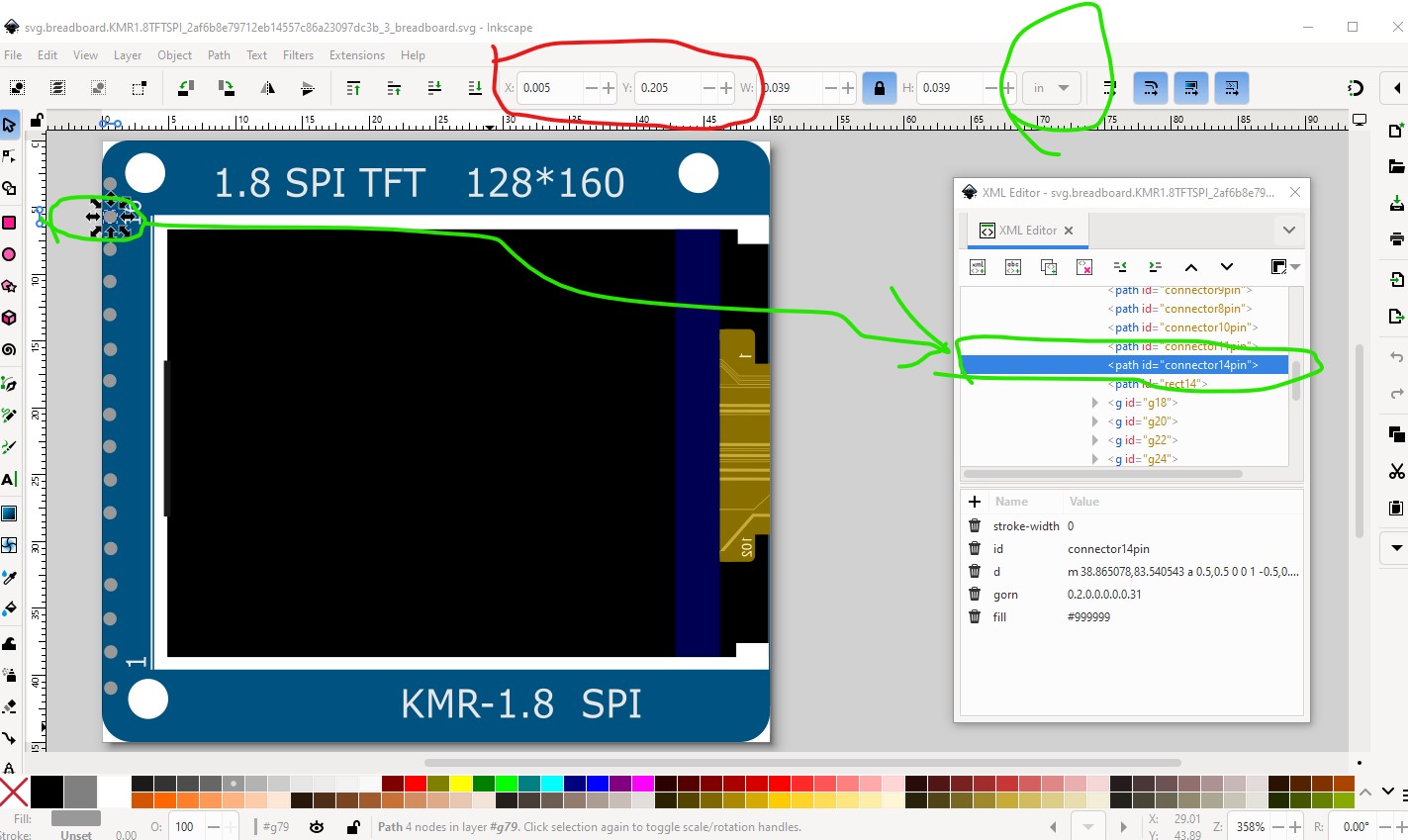
The first pin is aligned to the grid, but the rest are a bit long and don’t match the grid (which is 0.1in to match the breadboard.) In the svg that looks like this
The first pin which aligns with the grid is at 0.004in 0.108in, the second needs to be at 0.004in 0.208in but in fact is a little shorter and in a very small amount in x (which isn’t noticeable) :
You want to adjust the x and y values to be exactly on 0.1in boundaries and all will be fine. This is a very good start to part making, most people make a lot more mistakes than this!
Peter
Thank you very much, I will follow through them and upload the corrected part here, and mention about the part shortcomings from another place that I have posted, linking this thread.
With gratitude
Ninaad Das