Hello to all,
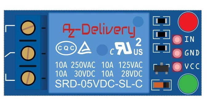
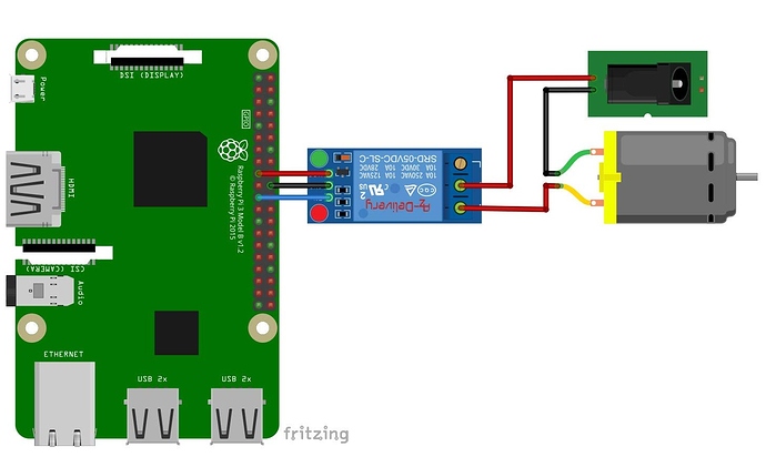
looking for the fzpz file of the KF-301 module, I can’t find it, I always find the KY-019, or the KF301 connector. Also searching on google I don’t find, but I find images of schemes made with fritzing with that module as an image, someone can you help me find it please?
I can send image of the file I am looking for but as a new user do not make me attach
A google search for “fritzing part srd-o5” (the part number of the relay) turns up a variety of sources. Some are no longer available, but several are (there are a couple of posts here in the forum that may be suitable.) As well there is one in a project which can be obtained by going to
and right clicking to download the .fzz file. Load that in to Fritzing and in the temp parts bin is the relay part (which can be exported by right clicking on it and choosing export part.)
Peter
This source is no longer available. Does anyone know other sources for this relay module KF-301 ?
A new web site server was rollout recently. Looks like something did not get ported over. @KjellM, can you have a look? Gives a 1020 accessed denied error.
@tnn85 The google search for “fritzing part srd-o5” still finds a reference on github: https://github.com/bluewalk/Fritzing-Parts/tree/master/SRD-5VDC-SL-C
From there, click “Go to File”, click “SRD-5VDC-SL-C/SRD-5VDC-SL-C.fzpz”, then finally “download”
@microMerlin Thx. I have tried this part already but this is only the relay itself, not the complete relay module with input circuit (LEDs, resistors, PNP transistor). I wonder if the part accessible behind the unreachable link is the module I am looking for.
The old server allowed public access to its file structure, and more and more bots were just scanning those files. The misuse was getting too high. That is why user profiles are now only visible to logged-in users, and those deep links to files are not possible. It is also one reason editing and adding projects is currently disabled, as we have to rework the editor.
You can still access the file by using its project slug. Remove the file structure part and append the slug to fritzing.org/projects :
https://fritzing.org/projects/iot-switch-onoff-220-240v-device-with-nodemcu-5v-r
Hello, @alex77k12! did you find this module? I’m looking for this same one. If you know where seek, I’ll thankfull. Tks a lot.
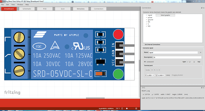
Hello there! i look for this part too, but it seems no one has it yet. so i try to make it myself, and hope it may help you…
KF-301 Relay.fzpz (25.7 KB)
this may not be very accurate for the size in pcb
i might update it soon…
Not a bad job for a first part, but a few problems: in breadboard
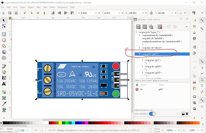
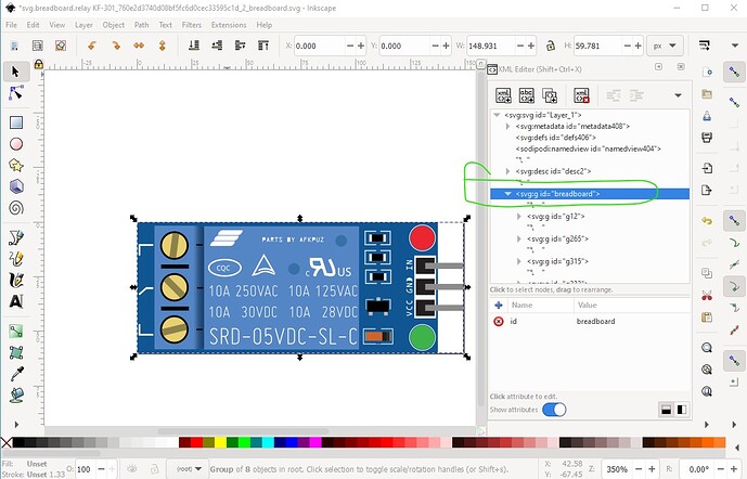
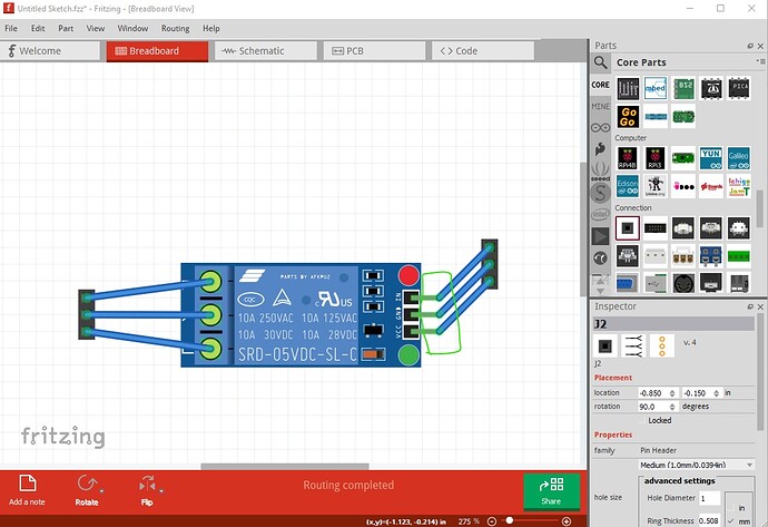
you need to add terminalIds to the 3 right side pins to move the connection from the middle of the pin to the right end of the pin. The definitions are in the fzp file but not in the svg. As well you need a layerId called breadboard in the breadboard svg because without it your part won’t export as an image (the wires will appear but there will be a blank where your part should be!) To fix that just change the id of the enclosing group to “breadboard” like this:
current (displayed in Inkscape)
corrected
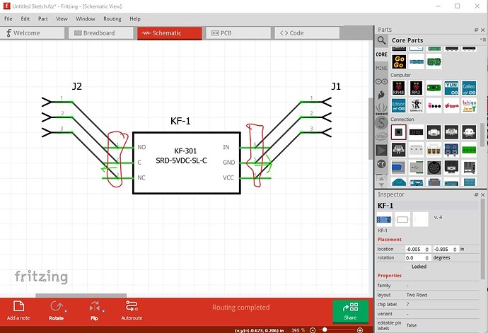
In schematic the same issue exists
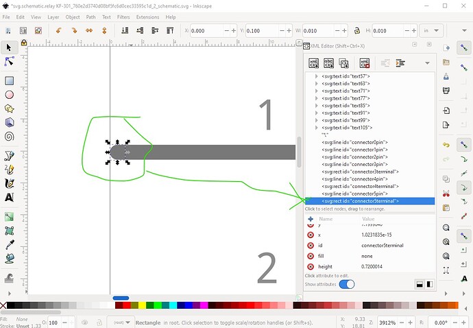
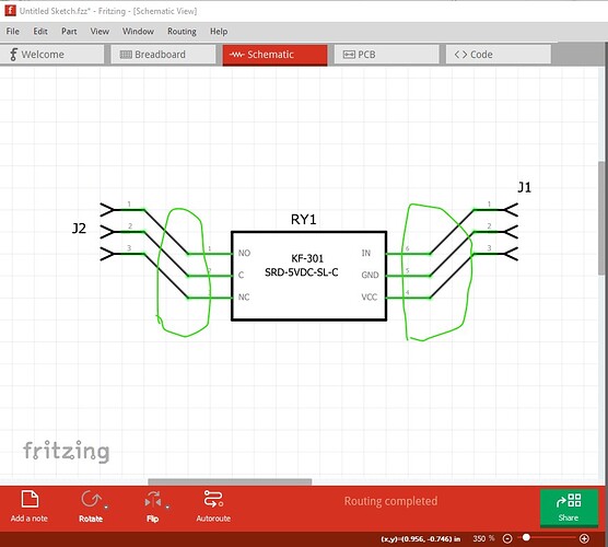
in this case some of the terminalIds exist, they just aren’t correct:
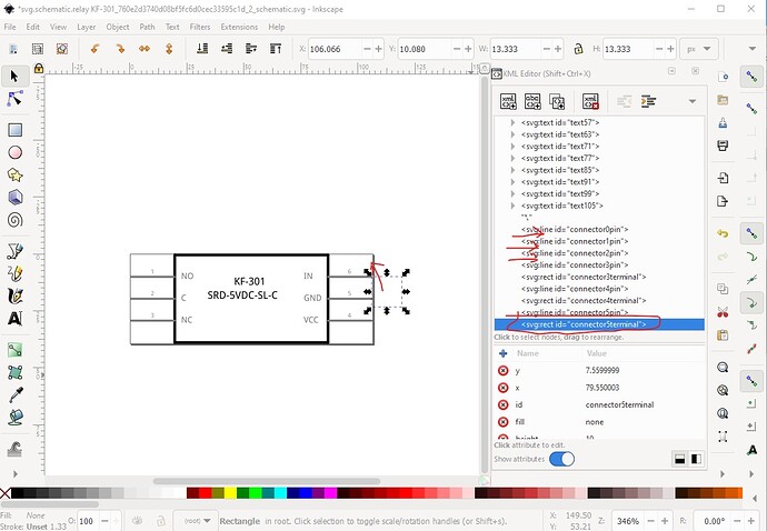
This one is too large and in the incorrect place, some of the others are missing. So
add a new terminalId the same width and height as the line (so it is a square) and position it at the end of the pin like this and set its id to connectorxterminal (where x is the pin number.) The complete corrected set looks like this:
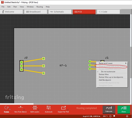
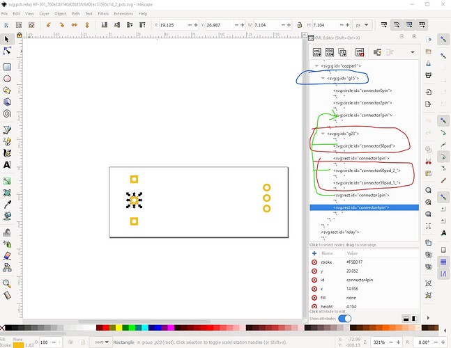
In pcb there are a variety of problems, the most important one is the lack of the copper0 group under the copper1 group
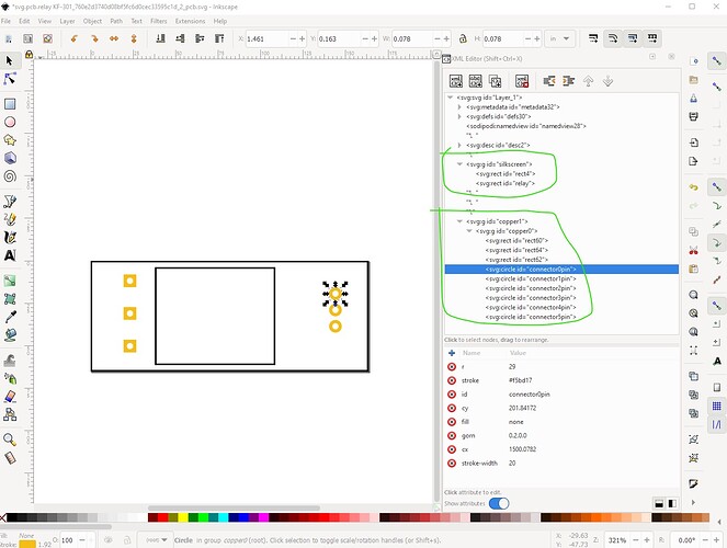
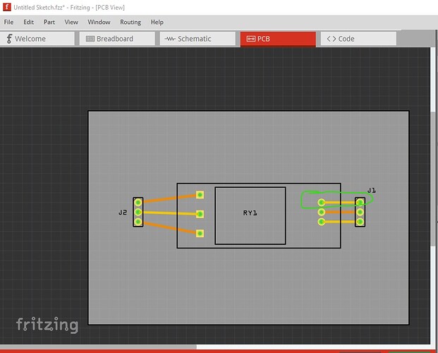
the blue circled group should have its id changed to copper0 so the part will appear on both sides of the board. As it stands it is an SMD part and will only appear on the top layer (copper1.) As well group g23 needs to be removed and the pads and pins below it moved under the copper0 group. Then I also moved the relay section from the bottom of the svg in to the silkscreen group where it belongs and removed the no display attribute so it shows up. As well I made all the pins be circles (the relay pins were the rectangles which will work but is non standard to give this which is the final pcb svg:
all these changes are in this part
KF-301 Relay-improved.fzpz (18.8 KB)
which looks like this:
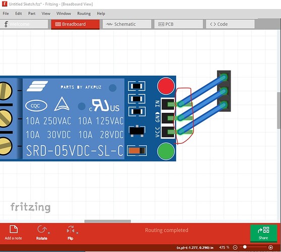
now the pins in breadboard connect to the end of the pin as they should. As do the pins in schematc:
and pcb has both the silkscreens visible and will route wires on either the top or bottom of the board:
Peter
Thank you very much! It’s nice to have someone fix it and point out where it went wrong. I know I’m still lacking a lot here. Thank you very much. by the way do you have any references or documentation for me to read on how to make it better? Especially in the schematics and pcb section because I’ve never designed it before
These two sets of tutorials apply to the current versions of Fritzing (most of the others are for older versions):
Peter
