I want to create the parte Sound Level Meter by DFRobot in Fritzing.
I’ve created a svg file to import it in Fritzing. In the partbuilder the picture of the part itself is visible, but after creating it, it diappears, while the pins stay visible.
Here is the svg and the fzpz filer Sound Level Meter.fzpz (221.9 KB)
For whatever reason, after creating this post, the part isn’t visible here too. But when I open the scg file in Microfot Edge for example, it is there (exacly like in Fritzing). So I’ve added an png picture of it.
except for 3 connectors. First try and upload the breadboard svg file you are trying to load. If the forum says it is corrupted, zip the original svg file and rename the zip file to .fzp then upload it (upload is 7th icon from the left on the reply menu.) Probably the svg is not in the correct format, but without the svg I can’t tell.
I don’t know what I’m doing wrong? I’ve uploaded it with the 7th icon. When I open the file, i get the image as shown in the png in my second post…
I will try it again. I zipes it and renamed it to .fzp. I hope this works Sound Level Meter.fzp (26.9 KB)
I get the png file of the board for the Sound Level Meter.fzp, but that isn’t sufficient for a breadboard svg file. To make a part you need to create an svg file that reflects this with a svg editor (I use Inkscape.) In theory you can embed the png in an svg, but it has never worked very well, and Inkscape can import and try and convert the png to a svg but that doesn’t work all that well either (I believe there is a section on doing this in Old_Grey’s video tutorial series available here):
but neither I nor he have ever had very good luck with it. There appears to be a pdf layout file on github here that would be a good start to making a part:
as it has both the layout and the sizes. If you like I will make a part when I finish one I am doing for someone else.
I’m sorry, I zipped the wrong file. I zipped the png instead of the svg. Here is the svg file I used to make the part in Fritzing zipped and renamed to .fzp: Sound Level Meter.fzp (111.5 KB)
When I import this to fritzing (Load image for view…) it is visible in the Parts Editor and I can select the pins and give them a name. But when I save it and want to load it into a sketch, the board itself diappers.
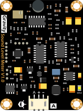
I used the png file from the DF Robot side to create the part: Gravity__Analog_Sound_Level_Meter_SKU_SEN0232-DFRobot (Board Overview)
This is a png picture, which I importet to Inkscape and addes the three pins.
The pfd you shared is black-and-white, this is why I used the one from the DFRobot wiki.
I imported the svg file to Fritzing, not the png. I just created it to show it to you. But isn’t it ok to use a png file (like the one from the DF Robot Wiki) to create the part in Inkskape? Does it have to be a pdf file?
It looks like parts editor (aside from being brain dead and not worth using) is objecting to the lack of a layerId on breadboard. In this part I made a number of changes: in the breadboard and schematic svgs, added a breadboard layerId and defined the connectors (which wasn’t done in the original.) I ran it through FritzingCheckPart.py to both check for errors and remove px from the font sizes (which is likely what wsa screwing up schematic.) At first glance the image appears fine (I suspect it may have problems when scaled though, although I didn’t try it.) If you unzip this fzpz file you will get the fzp and the 3 svg files that make up this part to see what changes I made from your original svgs.