This is a continuation of another thread that went off topic.
Thanks Peter for making this. I’ve been playing with it over the weekend. It’s not ideal (as you say), but also I sometimes need to common some of the pins together and your text label idea doesn’t allow me to do this.
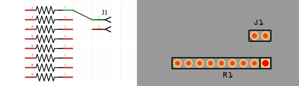
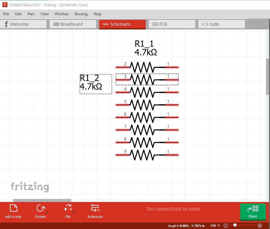
Inspired by your idea, I’ve been working on the original and have modified it into sub-parts, but with individual legs this time. I’ve given it useable legs to both ends of each resistor, but bussed them altogether in the fzp (as you did).
It seems to work as desired, see screenshots below, although I’m sure the part checker program will throw a wobbler with all the pins having the same name!
It will but can be safely ignored. The case where the names must be unique is fairly rare (everything else in the family and variants must be identical between two variants of a part) so it is rarely a real problem. I don’t think this should trip any bugs (although it may.) My original aimed to be a general purpose part, there is nothing wrong with making ones that are more specific (except you need more of them ) to reduce work in a project. I was thinking of suggesting that you could do something like this for your specific needs but figured you would figure that out!
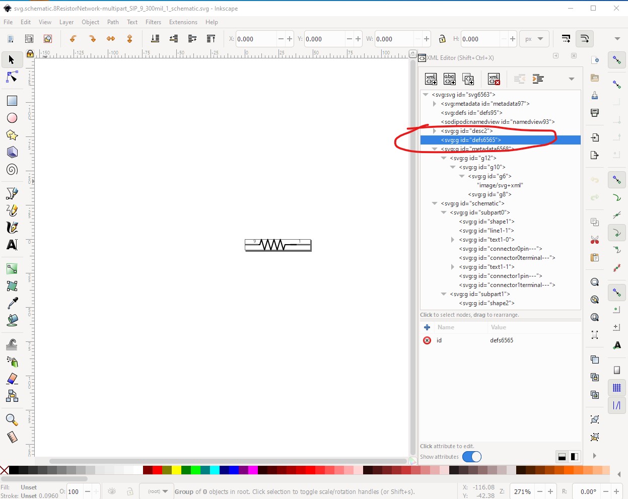
No. Spoke too soon about no bugs (although this is a limitation rather than a bug), you look to have been hit by a Fritzing limitation. The tiny subset doesn’t support defs (although the renderer will usually render them.) What has happened here is the export of the part to the temp parts bin has stripped the defs in schematic leaving this:
and the actual schematic svg that this came from (right click on it and select “save image as” to get the svg downloaded)
this is from the part “8 Resistor Network-multipart.fzpz” exported from the temp parts bin then unzipped. The loader has stripped the defs from the svg when coping it to the temp parts bin, leaving it broken as there aren’t defs for the elements any more. That in turn breaks the renderer when it tries to render the part. Moving the defs in to the actual xml should clear the issue though.
edit:
Changed my mind. This should be reported as a bug. It appears the render-er now processes defs so the exports (to the temp parts bin and to svg export which AFAIK both strip defs) should now copy defs so that parts are consistent. If the render-er will display them, then they should be copied to the new parts as well.
I don’t understand what the id=“defs6565” does and I’m not sure what “Moving the defs in to the actual xml” means either. Is the xml you’re referring to, the .fzp file?
On the subject of bugs; As I mentioned before there is a strange thing that is more of a cosmetic bug. If you connect any of the bussed pins to anything else in schematic view, then the rats-nest doesn’t appear in PCB view unless you move one of the parts. This only seems to happen on parts where the bussed pins are separate and not overlapping (as in this part).
fzp is xml, but so is svg. defs is an optional element for svg files that allows (among other things) creating a reusable template for graphics to be used elsewhere in the file. Due to the way (I expect) that Fritzing merges multiple svg files, from multiple parts, the defs information gets lost. It is outside of the layers/groups that Fritzing processes for the part graphics.
“Moving the defs into the actual xml” means replacing each reference to what is defined in the defs block (defs means definitions) with the actual content of the element in the defs block.
Inkscape can be convinced to do that by saving as “Optimized SVG”. “Plain SVG” might do it as well. Other Editors might have similar options. The ‘optimization’ tool that Inkscape uses is also available standalone, so it might be possible to run that after saving from any svg image editor.
I just did a search across all of the svg files included in the core parts library. I found 545 images that contain a “defs” entry. Ouch. It might not be that bad. My search did not check if the defs element was empty, or if what it defined was actually used.
Would you please post the .fzpz file for 8 resistor network multipart? The copy in the .fzz file doesn’t have the needed defs and I can’t immediately find a part that does. I had assumed you were using defs to simplify the svg but perhaps your editor is doing so without your knowledge. With the original xml from the fzpz file I should be able to show you what to do to eliminate the defs.
8 Resistor Network-multipart.fzpz (5.5 KB)
Here is the latest fzpz file, although it’s not much different from the one at the top of this thread.
I was using an existing part as a template when I made this part. All the stuff I didn’t understand I left in and I just modified the sections I needed. Is there a stripped down version of a part that I could use as a template for making parts like this?
Thanks
Turns out the problem is bugs in the implementation of buses in subparts, not your svg as I had assumed. Your schematic svg is properly configured with no defs, but the export to the temp bin is wrong (and looked like there were missing defs.) I’ll open a ticket on github and anyone interested can look at the issues there:
Well done @vanepp, that looks pretty comprehensive. I’m guessing the missing rats-nest I mentioned is associated to the bugs you have reported?
Sorry I keep finding bugs!
One other question about subparts in general; How do I get a label to appear in the same way as a part without subparts? I notice that parts with subparts don’t have labels.
The resistors in the example above need to have a label. I need a copy of the label for each subpart that follows it around wherever I put it. If I group resistors together then I would want to turn off duplicate labels. Logic gates don’t need a label, so I need a way of enabling or disabling labelling altogether depending upon the part.
Maybe or it may be yet another bug, I guess we will see. Hopefully with examples of what is wrong a better fix will be forthcoming.
no need to be sorry for finding bugs. Getting a reproducible bug report is key to fixing the bugs. The most work is usually trying to reproduce the bug so you can be sure you fixed it. I have been trying for 4 or 5 year to reproduce a bug that corrupts the routing database by making changes in multiple views so far without being able to reproduce it so it can be fixed.
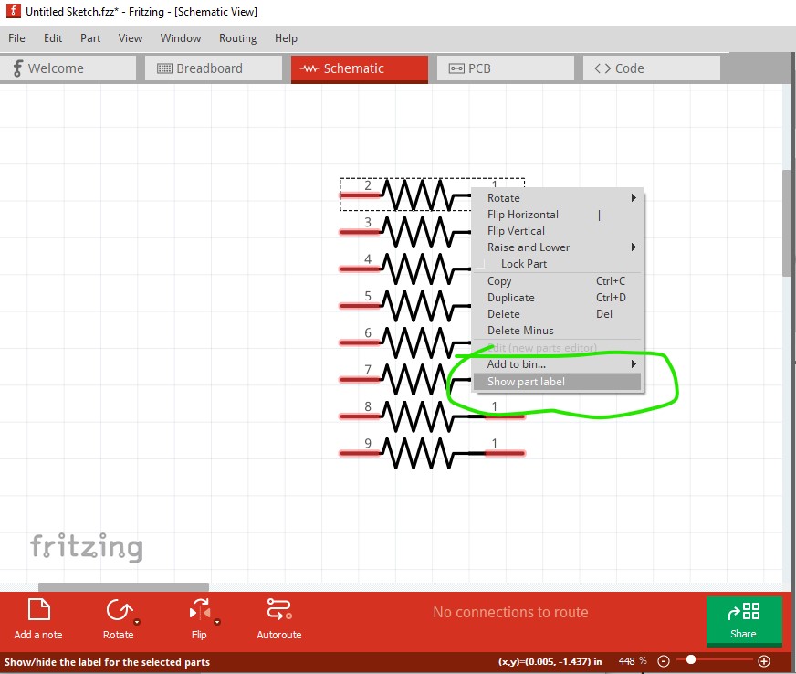
Yes, there is per element labeling now, it just defaults to off. Right click on the element you want to label and click Show label (or Hide label to remove it.)
Ah, that’s where it is! Perfect! I was searching in the fzp to enable the label.
Is the “part label” the only editable label? How do you make other labels editable, such as “chip label”, etc? It would be great if I could enable the drop down menu for “resistance”, like what’s available on the core part resistor.
Some can be done by properties (to select between versions) but the resistor values use special code and need your resistor to be part of the family resistor (which expects a single resistor and will try and change the color band values and thus probably won’t work here.) It would be nice to have an api that would let you do things like this, but it isn’t present in the current code.
Not that I know of. The code knows to show a pull down box for the different variants of a part, but nothing else as far as I know. What I would like is a code mode to make an editable property available, with the values in a property or other field of the part so you can define both the property and the values it can have (with an option for user set values if you want) so you can do this with any part, but it isn’t in the code as far as I know (and may well have issues I haven’t though of as well!)
Yes, that would be ideal and what I was hoping for. One for the wish list if the developers run out of bugs to fix!
An annoying bug that I can’t pin down, is the right-click-label-move bug. It doesn’t happen every time, so I’ve not mentioned it before. If you load some parts in Schematic and move the position of a few labels, when you right click on a label to edit it’s properties, the label jumps away from the part by a certain distance.
It may be related to this open issue on github, or be a new one. If you can find a way to reproduce it reliably open a bug on github. The problem with the intermittent bugs is reproducing them so you can verify your fix worked.