How do I make sub-parts with a common pin?

Thanks for all your suggestions.

I’m not familiar with busses. Are there any parts available that use buses, so I can have a look how they work? In core parts for example.

Now that buses are now allowed in subpart parts, has anyone ever made a part with buses and subparts?

The arduino Uno is one in core parts that uses buses. Buses are pretty easy, the fzp file looks like this:

<buses>
  <bus id="bus0">
    <nodeMember connectorId="connector1"/>
    <nodeMember connectorId="connector2"/>
  </bus>
</buses>

you set the pins you want in the bus as nodeMembers. Here is the test part I tried last night (it shorts the gate output and the input so isn’t a real part though!) out of a subpart part to see if this was fixed. That should give you most of what you need. The difficult part will likely be figuring out how to represent the bus part in the subparts. I expect something like a net label with “bus” in it at the top of the resistor will work best. The fzp file from this test part should give you everything you need.

74x125_test.fzpz (9.7 KB)

here pin 2 is bused to pin 3 and thus both light yellow when either is selected (this is on Fritzing 0.9.9 I don’t know when this was fixed though.)

Peter

<bus id="bus0">
  <nodeMember connectorId="connector1"/>
  <nodeMember connectorId="connector2"/>
  <nodeMember connectorId="connector3"/>
  <nodeMember connectorId="connector4"/>
</bus>

By adding a couple more lines to your fzp joins together pins 3 & 4 on the second subpart too, but I notice that it doesn’t join all four pins together though. That would have made things very easy!

Here is a functional SPST relay part with 2 subparts and 2 buses. I had some cleanup planned for this part that I never got around to, but it seems to be working, and includes examples of all of the sections you should need.

SPST-D31A-Relay_1.fzpz (5.4 KB)

Here is what the schematic from that looks like:

svg.schematic.D31A-relay_schematic

@vanepp That is a direct paste of the svg image. I did not even resize it after upload. The forum software was updated a while ago, and now handles the small svg images with units of “in” and dimensions of less than 1 inch.

SPST-D31A-Relay_1.fzpz
I’m struggling to see how this part works, what is the purpose of pins 3 and 4? Is there a way to change this to a normally closed relay? It only opens as a normally open relay in Fritzing and pins 3 & 4 are hidden.

It doesn’t connect them together physically in the drawing, but does do so logically, so a connection to any pin is also a connection to all the rest. That is why I suggested that the bus pin in each resistor may need a net label type tag to indicate it is part of a bus. In schematic this has a consequence: if you have two pins in the same bus it will only connect to the bus once, so you may not be able to make a connection to an open pin if there is already another connection to that bus. The usual way this is handled is putting all the pins on top of each other in schematic (or as I usually do just remember that if a connection won’t complete it is already connected to that bus somewhere else!) So in the case of your sip resistor you can only connect the power source to one of the bus pins, it won’t accept a connection to any of the other 7 as there is already a connection so you need a way to indicate it is connected to a bus. Ideally you would be able to have a net label that took its name from the connected pin, but that functionality (AFAIK) doesn’t currently exist.

Peter

SPST-D31A-Relay_1.fzpz
Ok, I have just checked out the datasheet for the D31A and I can see that each side of the relay goes to two pins. I see why you (@microMerlin) want to common the pins now.
D31A

Ah yes, placing the part in schematic only a pair light up yellow, but I can see all four connecting in PCB view.

A strange thing I noticed is that if you connect any of the bussed pins to anything else, then the rats-nest doesn’t appear in PCB view unless you move one of the parts.

I will have a play with it over the weekend.
Thanks

I realized while I knew what I was suggesting, without a part/picture it wasn’t going to make much sense to anyone else. So a picture and a part of what I mean:

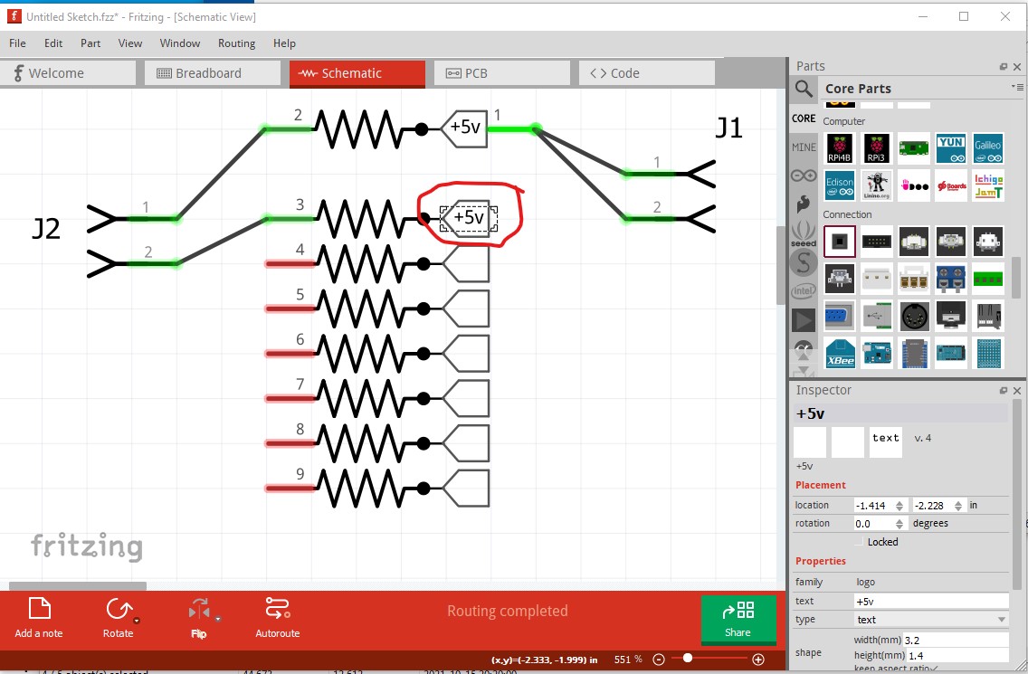
The “net label” is actually schematic text (with the size reduced to fit in the box.) The down side is that it doesn’t move with the subpart, if you move the subpart you have to manually move the label (which is a PITA!) but I don’t know any other way to do it. Here is the part that creates the above

8 Resistor Network-multipart.fzpz (6.1 KB)

it has the same moduleId as your posted part so you will need to delete that before you can load the new one. The 8 bused connections have 7 new connectors which are all overlaid on pin 1 and included in the bus (and the same happens in breadboard and pcb, 8 pins overlaid on pin 1) You probably don’t actually need the 7 overlaid pins in the bus, I expect this would work with just the image circled in red above and only one pin in the subpart definition although I haven’t tried that.

Peter

1 Like

An Arduino can not drive that many LEDs from a single data pin. For a 5V Arduino, with red LEDs (about 2V drop), and the 220 Ohm resistors, that circuit would ATEMPT to draw about 122ma from the pin. Which is only capable of about 40ma. With the same assumptions, if you want to drive 9 LEDs directly from a single pin, increase the current limiting resistors to at least 675 Ohms.

The suggested relay would work, although even that might be too much for a digital pin to drive. It would need to have less than 40ma pull in current. Better (LED direct, or relay) would be to use a FET to drive the load. A BJT transistor works too, but is less efficient. Another driver option is an SCS (Silicon Controlled Switch)

If that code is suppose to use PWM to control the LED brightness, it needs to use AnalogWrite, not DigitalWrite. If it is just supposed to be simple on/off, then LEDval should be “True”.

Also for either case, setting the value only needs to be done once. If it does not need to change in the code, the appropriate write could be put in Setup()

You’re correct Arduino isn’t enough power to give full power to all 9 at full brightness.
Which is why I said you would need to add in a relay to the circuit to turn on the external power supply. I’m not using an external power supply on purpose. I wanted to know how the voltage would drop from one LED to the next. The point of my post was that the circuit works with one pin controlling multiple resistors. Thank you for the tip I need to use analogWrite. I have not learned about using “TRUE” yet, only 0-255 & HIGH or LOW.

When using digitalWrite, true is the same has high. false the same as low.

A mechanical relay is “slow”. If you use one of the “digital” options, you could use PWM brightness control for the string of LEDs.

Yes I agree mechanical relay is slow. What do you mean by digital options? A solid state relay? The other option is using an actual string of LED’s with IC’s instead of just one color. with that I have power +/- with a power supply feeding the string where needed and a data pin.

Either a power transistor or a power MOSFET driven from the data line on the micro will do the job in a simple manner. The string of LEDs with a chip will work fine, but has extra code requirements (there needs to be an assembler driver to meet the chip timing requirements.)

Peter

I’m just now learning how motor controllers and transistors work my past experience with electronics was mostly with resistors and capacitors. If the device didn’t work we just swapped it out with a new one.

A circuit like this will do what you want.

here the micro is driving the base of the transistor with about 5 milliamps. Assuming the transistor has a gain of 100 (fairly common) the collector will sink about 500ma more than enough to drive your LEDs without loading the output pin of the micro (well less than the 40ma the pin can provide.) There is however an inversion through the transistor so where your LEDs used to light when the output pin was 0V the LEDs now will light when the pin is at 5V instead.

Peter

1 Like

Hello, thanks @Andrew177 for your help on this subject of how to make sub-parts with a common pin? I still need help finding the best way to do this, but this thread seems to have gone off topic, so I’ll start a new thread for those who were following it.