I have some 1000x1000 SVGs that I would like to turn into Fritzing parts. I know this sounds odd, but I would like these parts not to have much of a function; just a wire connection on the left and right sides. I would appreciate any guidance you could give me, thank you for your help!
These two tutorials on parts making apply to current versions of Fritzing. Note that making parts successfully is a complex process.
I lately learned there aren’t links to the videos in Old_Grey’s tutorial so you need to do a google search for the title and then they come up on YouTube.
that said it may be easier to upload the svg files (upload is 7th icon from the left in the reply menu) and specify what connections you want and get one of us to make you a part.
Thank you for the reply! I have the part ready in the editor, I am just having some trouble with one more thing.
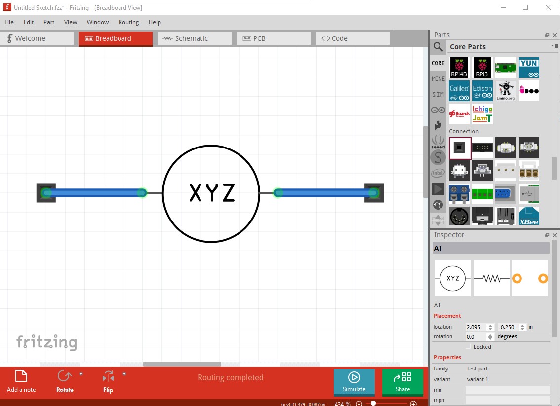
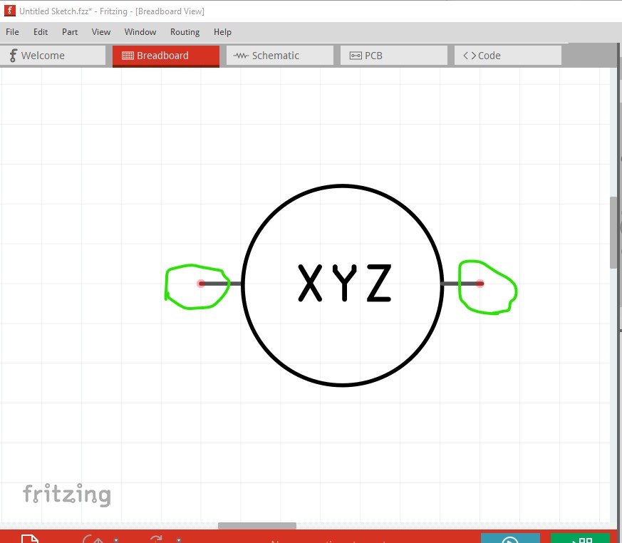
Attached below is an image of the new part. It is just a 220ohm resistor of which I have changed the breadboard view image. I would like for there to be a connection on the left and the right side that have the wire that comes out.
I would really appreciate some guidance on how to achieve this - and I know the part is a little bit unorthodox. Thank you for your help!
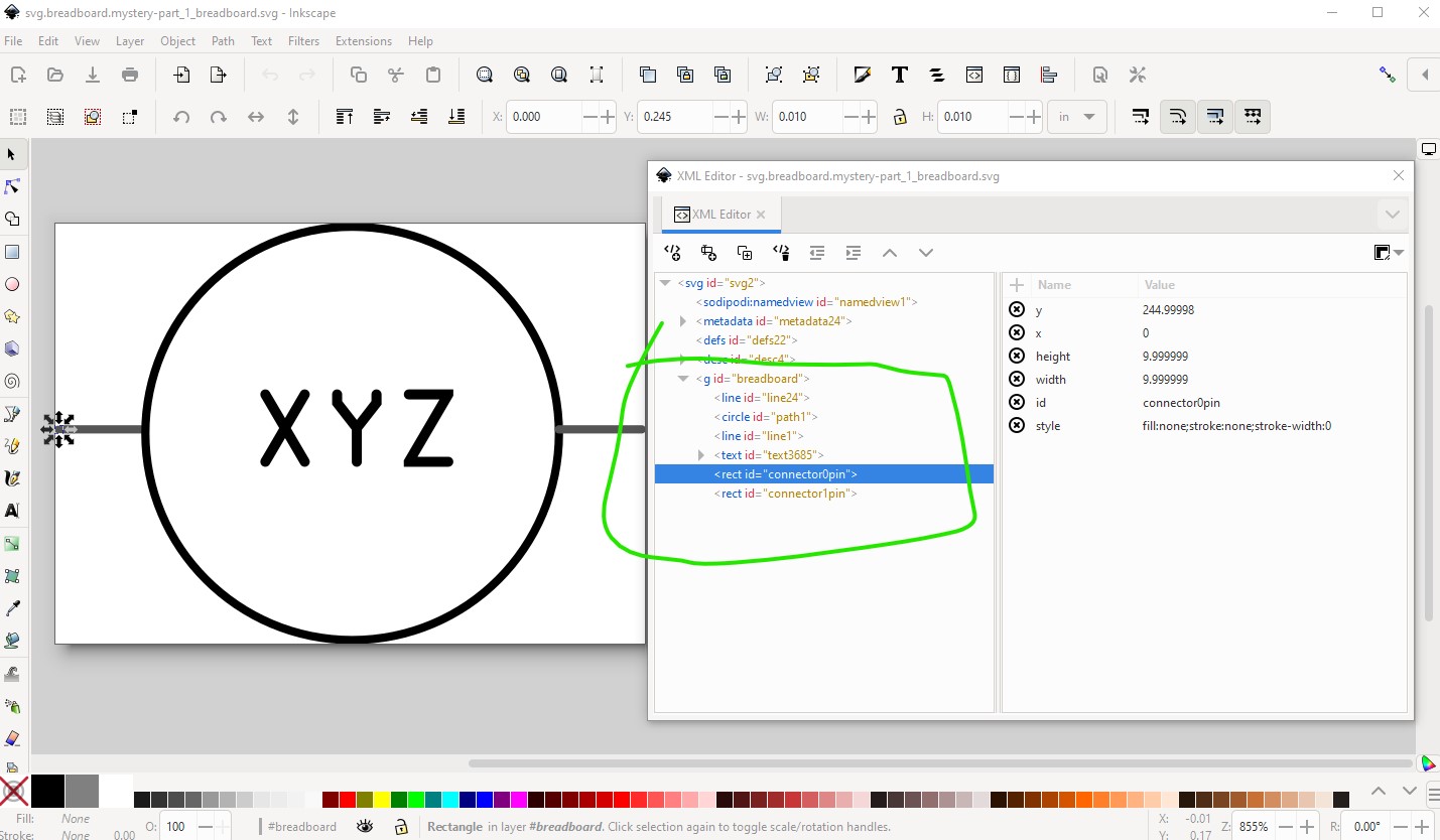
unzip the .fzpz file to get the fzp file and the 3 svg files for the part. Breadboard needs to look like this (with the layerId set to breadboard which needs to match the .fzp file in order for the part to export as an image.) The connectors need to start at connector0pin (and again match the definition in the fzp file) and in this case be on the end of the pin so the wire connects to the end of the pin rather than the middle of the pin. The entire part looks like this (here displayed in Inkscape)
here I didn’t choose to use a terminalId (which would have made the entire pin red but still connected to the end of the pin because of the terminalId.)