Ah, it becomes clearer. You are trying to modify a part rather than a sketch. This set of tutorials is how I do this task without using parts editor by editing the underlying files instead.
This series of video tutorials by Old_Grey covers parts editor and other topics.
As to your specific question here is how you do it using Inkscape (it should be similar if you are using another svg editor)
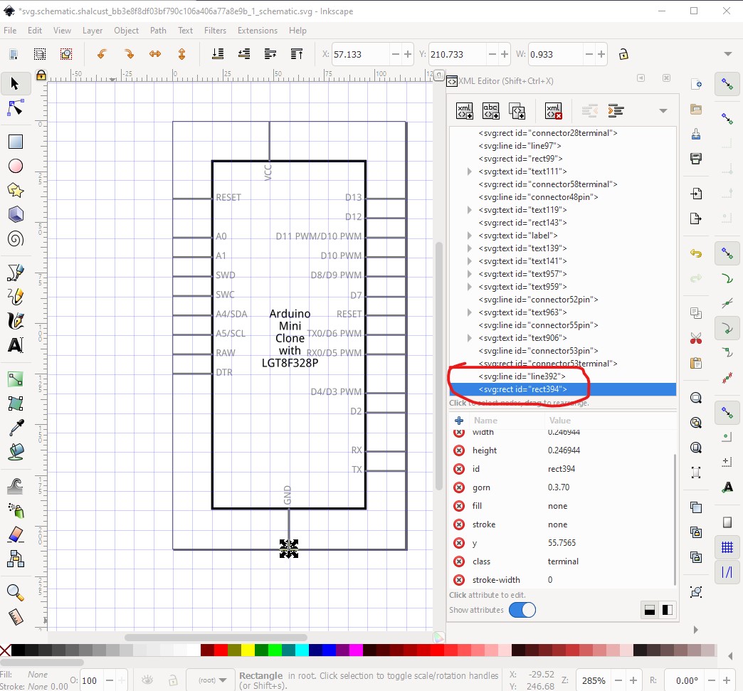
First you need to associate the connectorxpin connection with its associated terminalId, they are wrong in these two images. I chose this particular pin pair because the terminalId is the correct one for the ground pin that you need to dup to make this work.
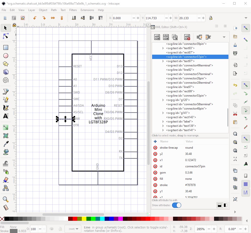
First I ungrouped the entire svg to make life easier (at the end of it all you need to do an edit–>select all and then group and set the id to schematic to set the correct layerId.) Then I moved connector53pin and
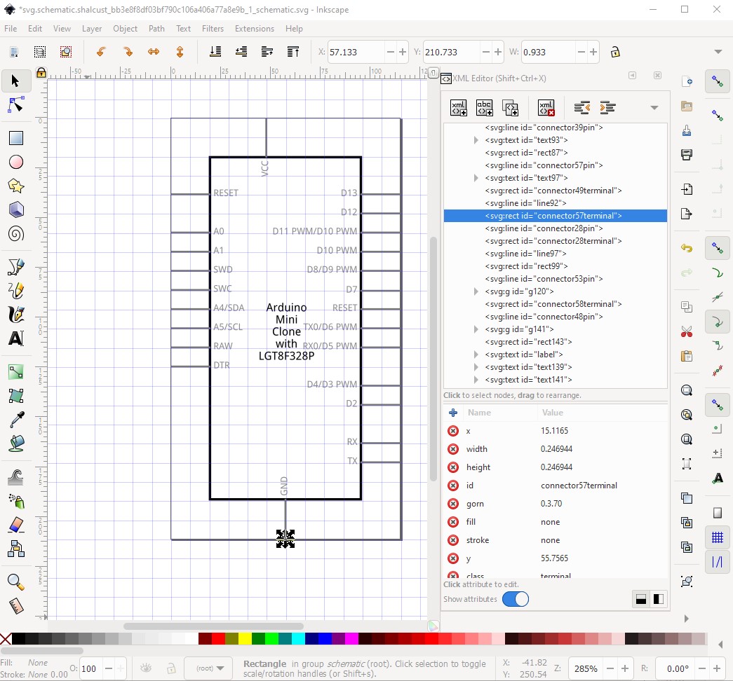
connector57terminal (renaming it to connector53terminal as it should be) to the bottom of the xml editor window.
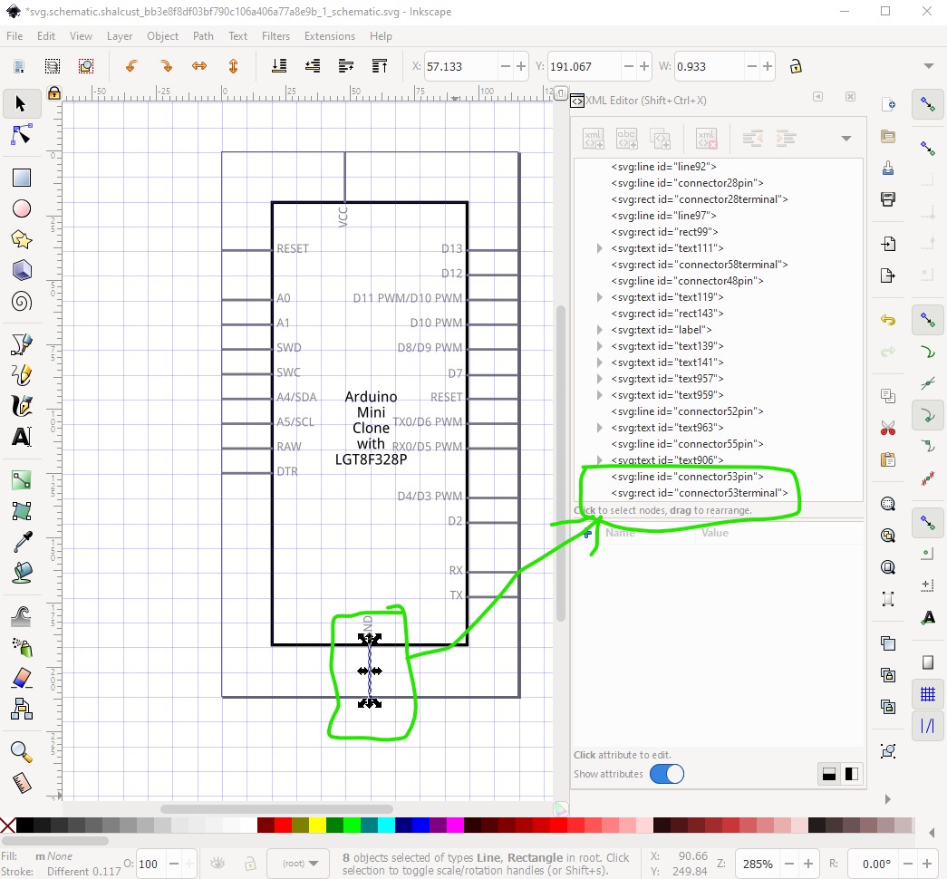
Then I selected both the pin and terminal and duplicated them which has an unexpected result:
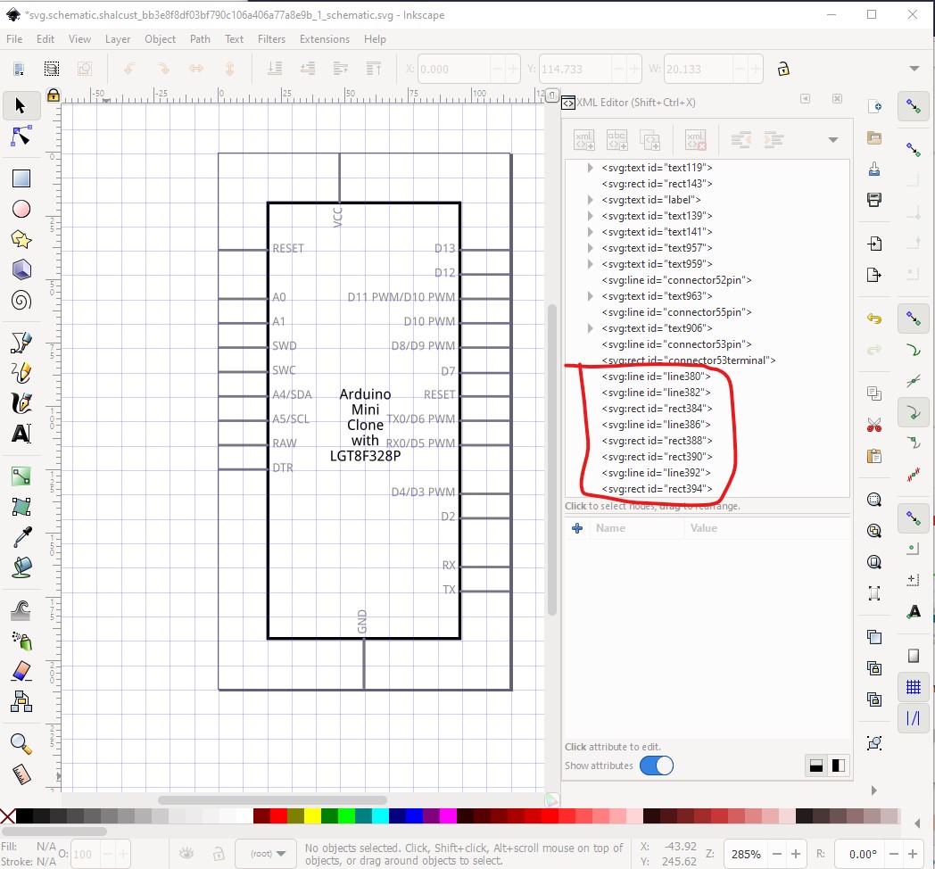
there are already a number of pins overlaid on the ground pin (probably from whatever you cloned this from.) So delete all of them except for one pin and one terminal like this:
now switch to the breadboard svg and find connector53pin (which is already correctly present in schematic) as a reference point.
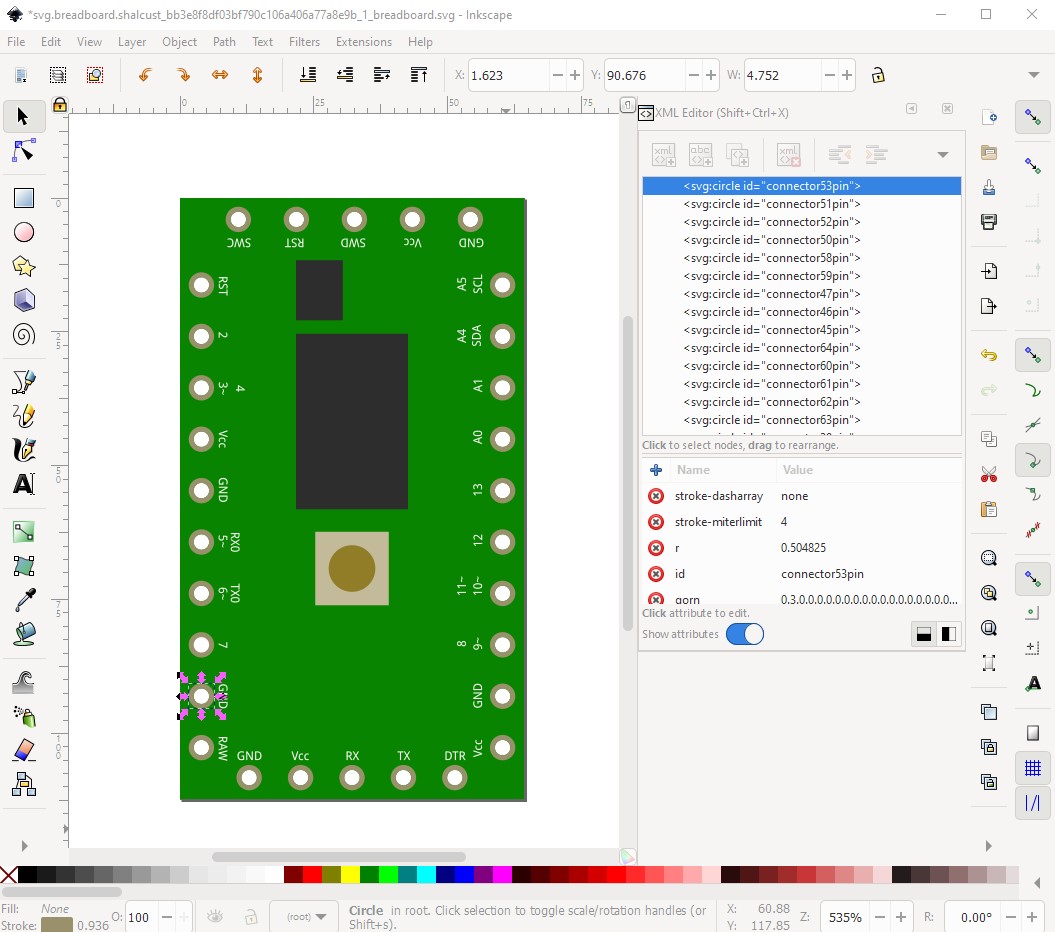
Now select one of the other ground pins connector56 in this case) to add to schematic.
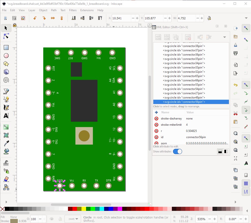
and change the id on the line to connector56pin and the rectangle to connector56terminal which overlays another ground pin on the same place in schematic. Note that once you have done all this you then need to adjust the bus configuration (internal connetions in parts editor) to place all the associated pins overlaid on top of each other in the same bus.

Do the same thing for any further connections needing to share a single pin.
Peter