Hello, I’m new to fritzing and want to make awesome device.
but i’m now struggling with some frustration. fritzing is lack of some parts.
if someone help me, i will upload the part made by me, and upload youtube video if i have time.
question is :
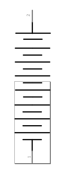
this is the 3S LIPO battery that i found on internet.
i want to upload the image, but this forum have restriction on new user, so i can only put one image on my topic.
I decided change text layer from “11.1V 3S LIPO BATTERY” to “22.2V 6S LIPO BATTERY”
and change schematic image to 6 along battery(now 3 along battery)
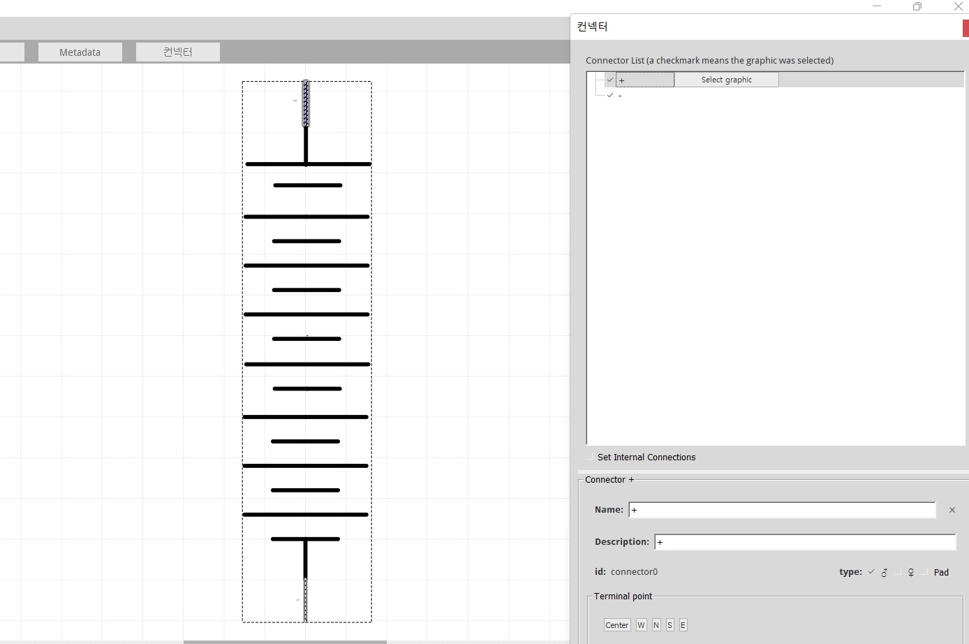
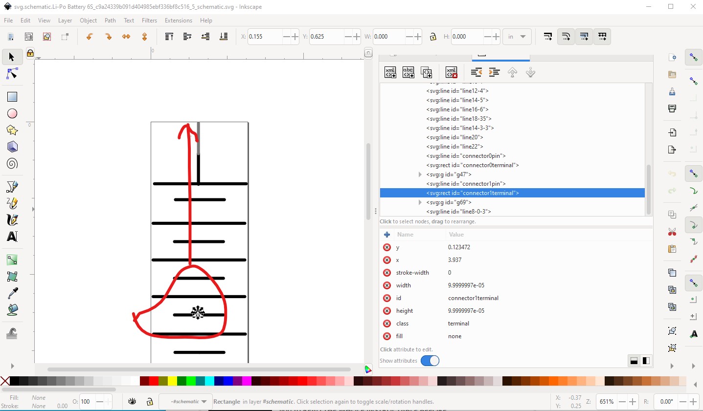
i opened svg image on the inkscape, and edited, result is like below :
I have no idea what size to match, what is the exterior line(thick line, maybe it is size of the model),how to extend exterior line and is there anything to do in inkscape before change connector location in fritzing part editor.
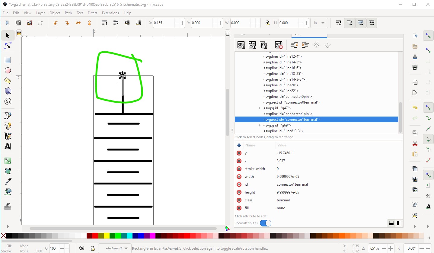
In this case you don’t want to do this. Schematic is an abstract view and the current schematic is entirely fine as is. You may want to edit breadboard to change the voltage on the battery however. In the image, you look to have not done (in Inkscape) an “Edit-select all” followed by a “Edit->resize page to selection” to reset the view box which will result in the image being truncated when loaded in to Fritzing. These two tutorials apply to current versions of Fritzing and will give you the necessary information to make parts: