You need the chip label in properties (or in the fzp file) not the label (which is U for IC and is the label of the chip.) Here I unzipped the fzpz file to get the fzp and the 4 svgs then edited
part.74LS04_980f2b69f7522fd48bea7098d8006ef4_2.fzp
for the label change from:
<properties>
  <property name="family">Generic IC</property>
  <property name="package">DIP (Dual Inline) [THT]</property>
  <property name="pins">14</property>
  <property name="pin spacing">300mil</property>
  <property name="chip label">IC</property>
  <property name="hole size"/>
to
<properties>
  <property name="family">74LS04</property>
  <property name="package">DIP (Dual Inline) [THT]</property>
  <property name="pins">14</property>
  <property name="pin spacing">300mil</property>
  <property name="chip label">74LS04</property>
  <property name="hole size"/>
here I also changed the family property from Generic IC to 74ls04. If it remains Generic IC the parts factory will rearrange the part if you change the chip type (which I typically don’t want, you may or may not want to swap parts though.) Note this is a schematic subpart part so the individual gates in schematic will move around independently, so be careful if you modify the schematic svg because its format is important. The pin names are also changed in the fzp file in the description property of the connector like this from:
<connector name="pin1" id="connector0" type="male">
  <description>pin 1</description>
to
<connector name="pin1" id="connector0" type="male">
  <description>IN-A</description>
the description field shows up in the data displayed when you hover over the pin. Replacing this:
<iconView>
  <layers image="icon/74LS04_1301646018940d479352cc70054d637c_1_icon.svg">
    <layer layerId="icon"/>
  </layers>
</iconView>
with this:
<iconView>
  <layers image="breadboard/74LS04_1301646018940d479352cc70054d637c_1_breadboard.svg">
    <layer layerId="icon"/>
  </layers>
</iconView>
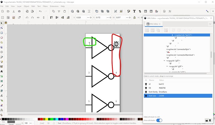
will make the icon that shows up in Inspector (the lower right window) from an 8pin chip to the correct 14pin chip as well. If I were doing this I would probably also increase the font size on the pin labels in the schematic svg (which would require an svg editor such as Inkscape) as they are currently rather small.
Like this in Inkscape
Here I changed pin 1 from a font-size of 2.8346 to 5 to make it slightly larger (there are actually proper sizes but the scale of this svg is non standard and I’m to lazy to convert it!) You then need to save the svg as plain svg and after exiting Inkscape either use a text editor to remove the px from all the font-sizes or process the part through FritzingCheckPart.py which will do that automatically. These two tuturials apply to the current version of Fritzing (and mine is how I make parts typically not using the parts editor!)
If anything is unclear feel free to ask!
Peter
