Hello everybody
I want to add a direct power supply to my electronic objects designed by Fritzing, simple transformer for AC 230V to 12V for example.
I have found this component : https://fr.rs-online.com/web/p/transformateurs-pour-circuits-imprimes/1213824, it seems to be ok for me.
Before to realize my PCB thanks to Fritzing I want to be sure to use correct component under Fritzing. It will be stupid if designed on PCB will not correspond to component.
I have found several example of Fritzing file of transformer with 2 secondary, no one with only one secondary and I did’nt know how to modify file to be absolutely sure that design on PCB will correspond to component.
Does anyone could help me with Fritzinf file of this simple transformer please ?
Or someone could indicate me another component with his corresponding Fritzing file ?
A google search of the form “fritzing part transformer” will find all the transformers with Fritzing parts available (and may tell you where you can buy them or may not.) Other wise you would need a custom part for the transformer that you listed (because there doesn’t appear to be one.) There are also a variety of Hi link modules with fritzing parts such as
which may do what you want (it is a regulated switching power supply not a transformer though.) There are also generic power supply modules (I think at least 3 of them, possibly with source urls where they can be purchased) if you search for “generic power supply” in the forum search bar. It is also possible to make a custom part for the transformer you listed if none of these other options suit.
Hello Peter
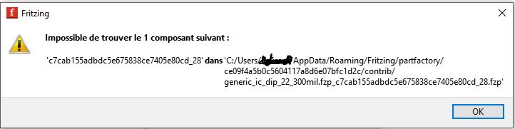
It’s another solution very interesting. As you say not transformer but directly DC 12V ! Thanks for your solution ! I get somethng strange when I try to import this file in my Fritzing, have a look in attached copy screen. In spite of this message I succeed to import it and continue my electronic assembly. So… What’s happen ?
I had already try your solution of looking for but the solutions found did not completely suit me : for example 2 output instead of only one, third pin for IN part and I really don’t know what it’s for… But since I’m a little stubborn , I would still like to try my solution so could you indicate me as to create from scratch a new component in Fritzing or to modify an existing one ?
It looks like you have a corrupted part in your user directories (I don’t thing it has anything to do with the new part which loads correctly for me.) If you don’t have a lot of parts in your mine parts bin this should fix the problem by clearing the user directories (but will delete all your imported parts!) I would expect the same will happen if you just start Fritzing without trying to load the new part though (since I don’t think it has anything to do with the new part.) For me (on Fritzing 1.0.4 on Win10) the part loads fine with no errors.
"There are two user directories (with your parts and the parts database) which don’t get touched during an install (to not affect your sketches during upgrades). On Windows they are in
c:\users\username\AppData\Fritzing\roaming\Fritzing (which is a hidden directory so you need to enable hidden directories in explorer) and
c:\Users\username\My Documents\Fritzing (where username is your windows id)
If you don’t have any parts or sketches you want to keep you can just delete those two directories and Fritzing will recreate them, or you can move them aside by renaming them if you want to keep something in them.
This pair of parts making tutorials cover current versions of Fritzing (although as you will discover making parts is complex!)
I lately learned there aren’t links to the videos in Old_Grey’s tutorial so you need to do a google search for the title and then they come up on YouTube.
If you run in to troubles building the part I can make one for you.
Hello Peter
It’s not so important, just “strange”, this message because finally component is correctly added in my “personnal” list under Fritzing. Some more precisions : I have 0.9.3 version of Fritzing (which is free) on a some old PC. I’m not sure but I think that it’s probably one reason of this message, as is compatibility from your version to mine is not done. I can start with your component. “Good” fix for this problem is to buy recent version of fritzing and a new recent PC, planned but no now
For video you mentionned, it seems to be a good tuto but… This man speak very fast for my level of english I’m french and even if manage to understand after several playing, it’s quite difficult. I will continue my search by looking for french video.
I can easily enough make a part for the transformer you specified if you like. It usually isn’t worth the work of learning to make parts if you only need one or two parts, it is easier to get one of us familiar with making parts to do it for you.
Wahooo !!! So cool !
I don’t want to disturb you but if you can ok, thanks a lot !!
So… Could you design transformer specified in first message of this post ?
Or, another solution, specify what ever you want which have these characteristics :
it must be able to be soldered onto a PCB, so not too big and have to respect normally step to be used as all other components
primary on 230V AC, it should be able to use in France
secondary on 12V AC, only one secondary
able to run with out current between 0.5A and 1A
General idea is to make a power supply for small assemblies based on Arduino cards and therefore connected to the sector. Don’t hesitate to ask me what you want if I have forgotten something.
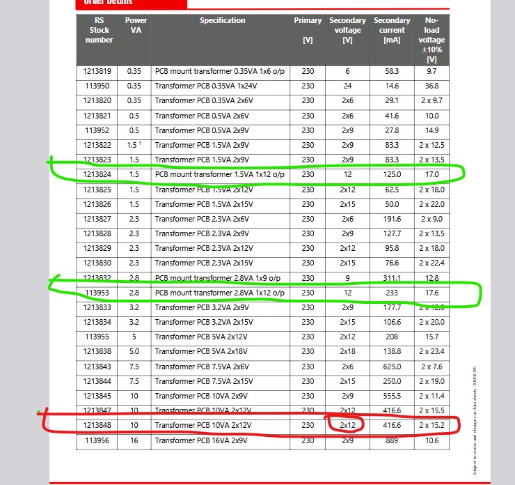
None of the transformers in your original post meet these requirements. The only one that can source that much current has a dual secondary (and would need both secondaries in parallel to get more that 417mA of output current.) A google search of the form “transformer 220V primary single 12V secondary 1A pc mount” doesn’t turn up much (and what there is is quite expensive.) They are probably cheaper on a site like Ebay or aliexpress but not much is turning up for me. Low VA types (2 or 3 VA which won’t provide the current you need) are quite cheap. Is the option circled in red here (the dual seconadry 416mA option) acceptable?
Well… Second one circled in green will be enough, I will make sure to have enough with output current of 233mA. To be honnest, I may have dimensioned the output current too much. If 2 circled in green don’t have same dimesions, is it possible to have 2 files (one for each other) ?
With this new “specification” of ouput current, do you think now that transformer indicate in my first message could correspond to my request ?
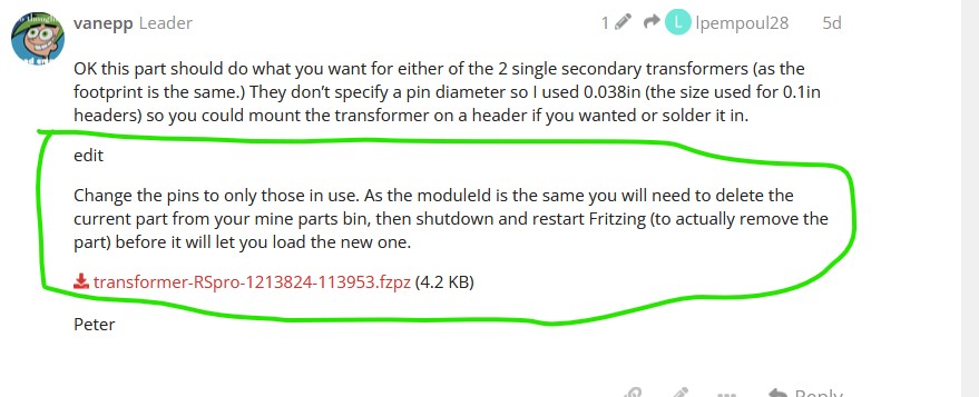
OK this part should do what you want for either of the 2 single secondary transformers (as the footprint is the same.) They don’t specify a pin diameter so I used 0.038in (the size used for 0.1in headers) so you could mount the transformer on a header if you wanted or solder it in.
edit
Change the pins to only those in use. As the moduleId is the same you will need to delete the current part from your mine parts bin, then shutdown and restart Fritzing (to actually remove the part) before it will let you load the new one.
edit2:
Remove the square pad on pin 1 as before need to remove the old part before you can load this one.
Hello Peter
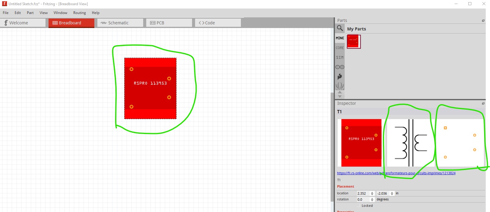
Your model seems OK, just one question why do you add so much pin (ten in total) ?
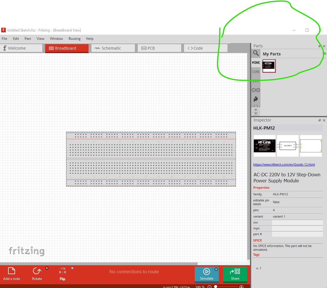
We only need 2 for primary and 2 for secondary, all other are not necessary and not physical present on component as shown in this copy screen.
I’m afraid of having to add pins on the PCB that don’t exist, do you see what I mean ?
Except error of my part, we need only 4 pin on this model.
The data sheet for the part indicated all pins were present even though unused. I can remove the unused ones without problem, a corrected version will be up in a bit.
Probably not worth doing. It appears the 10 pin version is only on the data sheet not a real part. The new part appears to match the actual part which is how it should be.
Hello Peter
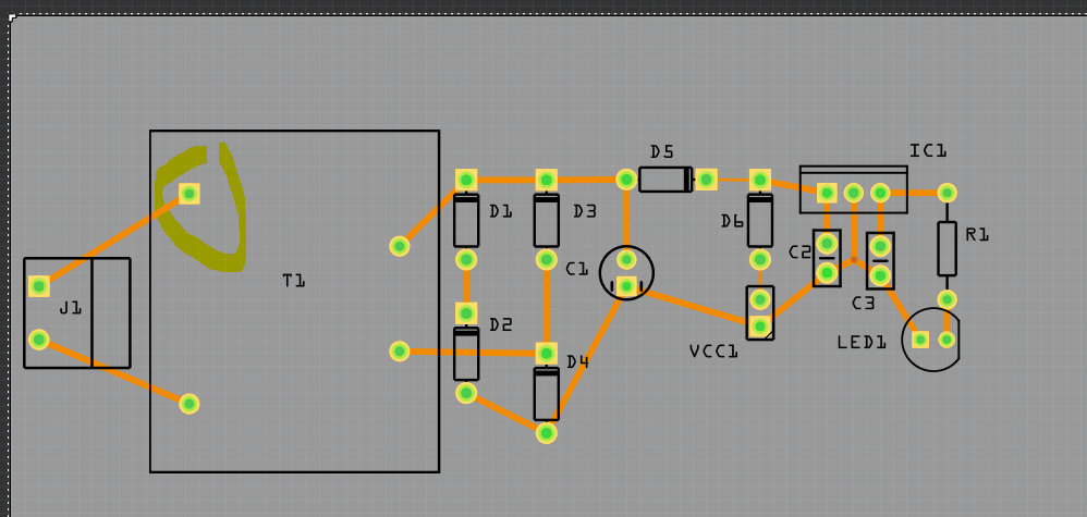
Sorry to insist but as shown in previous copy screen we can see only 4 pin. So, if we conserve all 10 pins, direct consequence is that we’ll have 6 holes drilled for nothing. And potentially these 6 holes totally useless can block me for drawing some pist.
I had try to modify your component but… Not so goog than you with fritzing and I have some problems with schematic view…
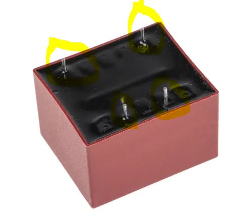
I have a look in datasheet and I’m sure that box of this transformer is same one for all version of it, same for 2 secondary or only one secondary for example. It’s reason, I think, why manufacturer plan 10 pins. But in case of version I need, only 4 pins are physically present. 6 other are just plan but not physically present.
Please, could you make another version of your component with only 4 pins ?
It is done. The part posted above has only the 4 active pins. Note the requirement to delete the old part before being able to load the new one in the edit. I expect you have the old part still and can’t load the new one.
Of course I have to add everything else with arduino (ATMega, quartz and capacitor), but it’s not a big difficult. Well, I just see that on PCB view your transfo as the first pin with a square instead of circle. Is it normal and wanted ? If yes could you explain me please (just to understand) ? Is it possible to do another one with circle as for 3 other pins please ?
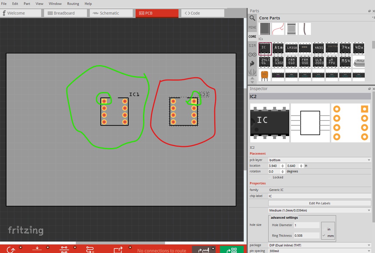
The square indicates pin1 of the part. In this case it doesn’t matter as the part will only fit in one direction but on something like an IC (which is symmetrical and may be on the top or bottom of the board) it matters so you can see where pin one should be. Here is an example with a generic IC in pcb
the one on the left is top of the board as usual. The one on the right is on the bottom of the board. Without the square on pin 1 it would not be obvious that the one on the right should be on the bottom of the board. I can easily remove the square from the part and will do so in a bit and reupload it.