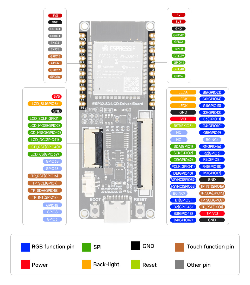
ESP32-S3-RGB-LCD-DRIVER-BOARD - WROOM-1-N8R8 - MODULE
Download:
ESP32-S3-RGB-LCD-DRIVER-BOARD-WROOM-1-N8R8.fzpz (94,KB)
Manufacturer URL: https://www.waveshare.com/wiki/ESP32-S3-LCD-Driver-Board
ESP32-S3-RGB-LCD-DRIVER-BOARD - WROOM-1-N8R8 - MODULE
Download:
ESP32-S3-RGB-LCD-DRIVER-BOARD-WROOM-1-N8R8.fzpz (94,KB)
Manufacturer URL: https://www.waveshare.com/wiki/ESP32-S3-LCD-Driver-Board
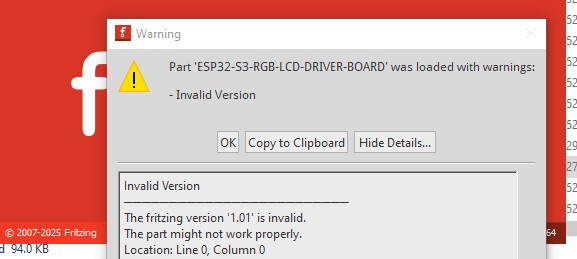
Your part has a number of problems. First the version number is incorrect which on Fritzing 1.0.5 causes this:
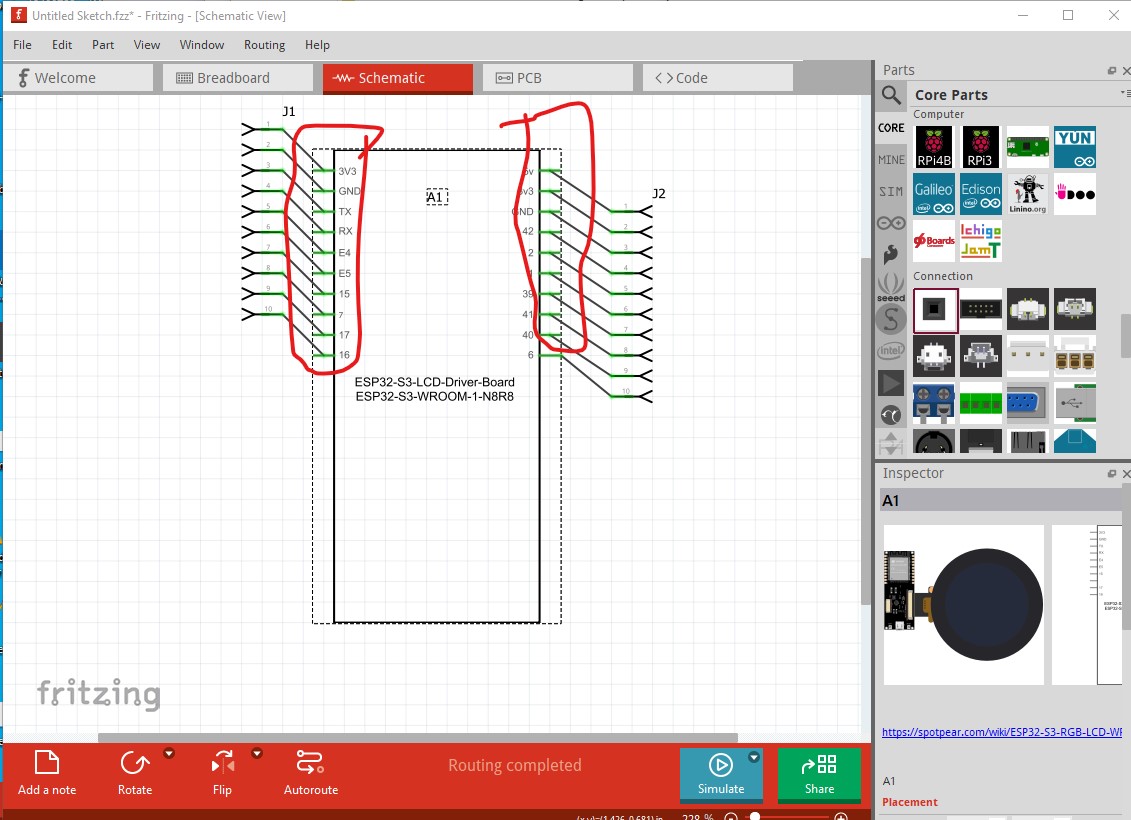
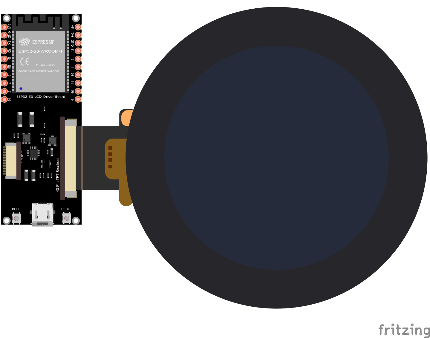
It probably (despite the message) won’t affect anything but is annoying as you need to hit OK to load the part every time. Breadboard looks OK, but schematic has several problems:
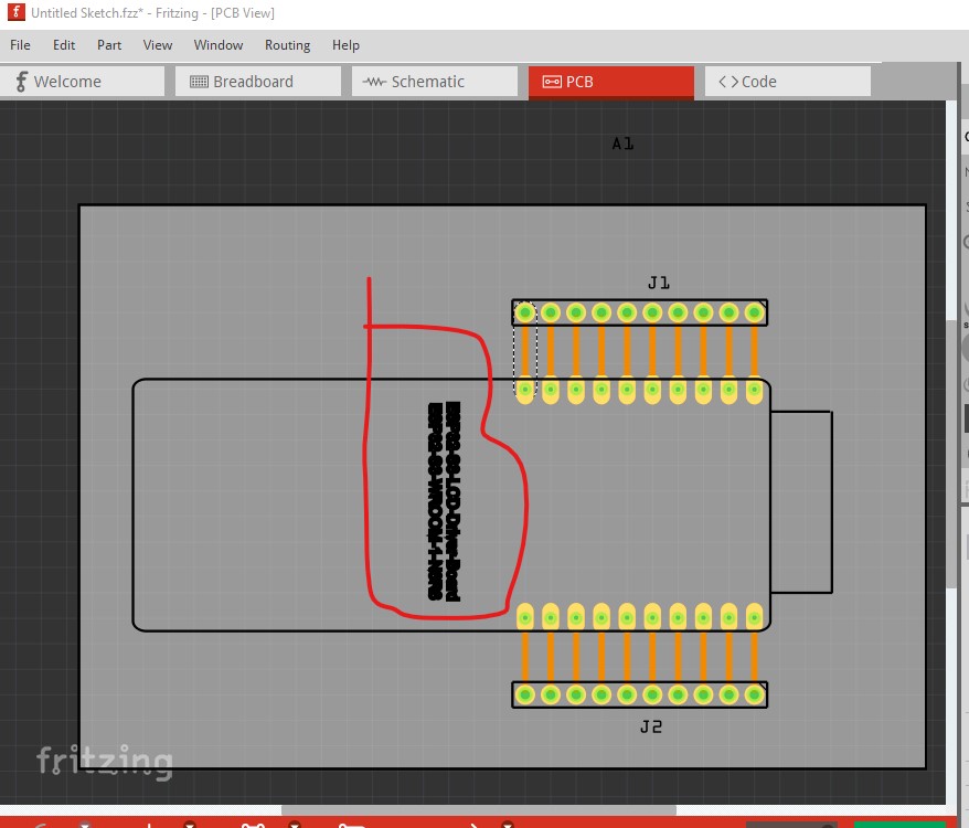
Most of the pins lack terminalIds which causes the part to be misaligned to the grid and the connector to connect in the middle of the pin (which is also where the grid is aligned) rather than the edge as it should. In pcb it is preferable to not add text as you need to change the part to remove it and the user can add it if they want it in the sketch. Something is also off about the font or font-size as it isn’t displaying properly.
Although it won’t affect anything operational, pin numbers are supposed to start at 0 not 1.
FritzingCheckPart.py flags the following errors (all to do with the terminalId being missing with the result we see in schematic.) and the not starting at pin 0:as well as bus errors.
Warning 14: File
‘part.ESP32-S3-LCD-Driver-Board_3a8cabfbb7b4e14f505215034786d62b_5.fzp.bak’
At line 347
terminalId missing in schematicView (likely an error)
Warning 36: File
‘part.ESP32-S3-LCD-Driver-Board_3a8cabfbb7b4e14f505215034786d62b_5.fzp.bak’
Connector0 doesn’t exist. Connectors should start at 0
Warning 35: File
‘part.ESP32-S3-LCD-Driver-Board_3a8cabfbb7b4e14f505215034786d62b_5.fzp.bak’
Connector0 doesn’t exist when it must to stay in sequence
…
Error 53: File
‘part.ESP32-S3-LCD-Driver-Board_3a8cabfbb7b4e14f505215034786d62b_5.fzp.bak’
At line 358
Bus nodeMember connector0 does’t exist
Error 53: File
‘part.ESP32-S3-LCD-Driver-Board_3a8cabfbb7b4e14f505215034786d62b_5.fzp.bak’
At line 363
Bus nodeMember connector22 does’t exist
Error 53: File
‘part.ESP32-S3-LCD-Driver-Board_3a8cabfbb7b4e14f505215034786d62b_5.fzp.bak’
At line 364
Bus nodeMember connector23 does’t exist
Error 53: File
‘part.ESP32-S3-LCD-Driver-Board_3a8cabfbb7b4e14f505215034786d62b_5.fzp.bak’
At line 365
Bus nodeMember connector43 does’t exist
Error 18: File
‘part.ESP32-S3-LCD-Driver-Board_3a8cabfbb7b4e14f505215034786d62b_5.fzp.bak’
Connector connector1terminal is in the fzp file but not the svg file. (typo?)
svg svg.schematic.ESP32-S3-LCD-Driver-Board_5e61efe62c1f6abfe2f6dfe59a2c935b_1_schematic.svg.bak
Error 18: File
‘part.ESP32-S3-LCD-Driver-Board_3a8cabfbb7b4e14f505215034786d62b_5.fzp.bak’
Connector connector2terminal is in the fzp file but not the svg file. (typo?)
svg svg.schematic.ESP32-S3-LCD-Driver-Board_5e61efe62c1f6abfe2f6dfe59a2c935b_1_schematic.svg.bak
You appear to have buses defined but not correctly as the ground pins are not bussed together as they should be. All of these issues can be corrected with information in this tutorial.
Peter
Hi Peter, I spent practically all day trying to solve the problems you showed me. I tweaked the file a bit, but I’m not sure I solved everything. I couldn’t set the first connector to “Connector0.” I modified the SVG files in Illustrator, but when I opened it in Fritzing, in the component editor, the pins didn’t appear selected with the images, and then when I selected everything again, the first pin returned with the ID “Connector1” instead of “Connector0.” However, after selecting all the images and configuring the terminal points, (in this way), everything works fine in Fritzing. Can you check the file?
ESP32-S3-RGB-LCD-DRIVER-BOARD-WROOM-1-N8R8_UPDATED.fzz (109,8,KB)
Please post the .fzpz file
It is ok thefzpz file is in the fzz file. I am working on fixing it.
Peter
OK, this was not a simple fix as there is quite a bit wrong.
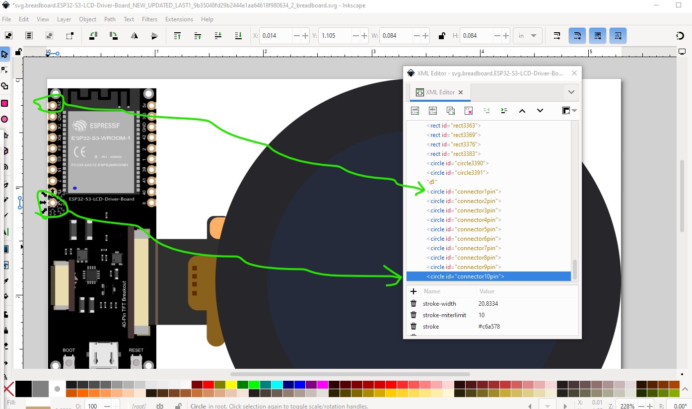
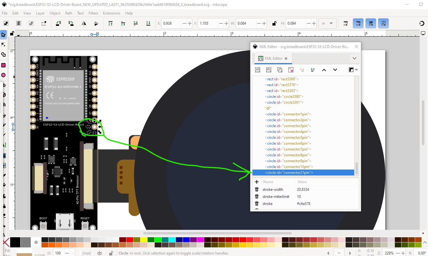
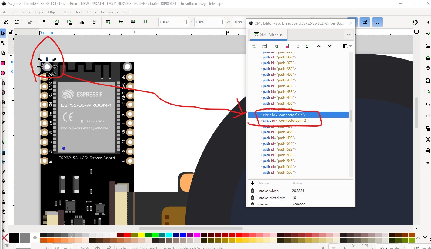
Starting with breadboard there are a number of problems. There is already a connector0 (although it is not the correct connector0) along with a bunch of other connectors that are not used. To change the part to start at connector 0 it is necessary to renumber the pins, luckily I have a tool which will do that while removing the unused connectors. So I started by moving the left side pins to the bottom of the svg (as that is where the tool needs them to be.)
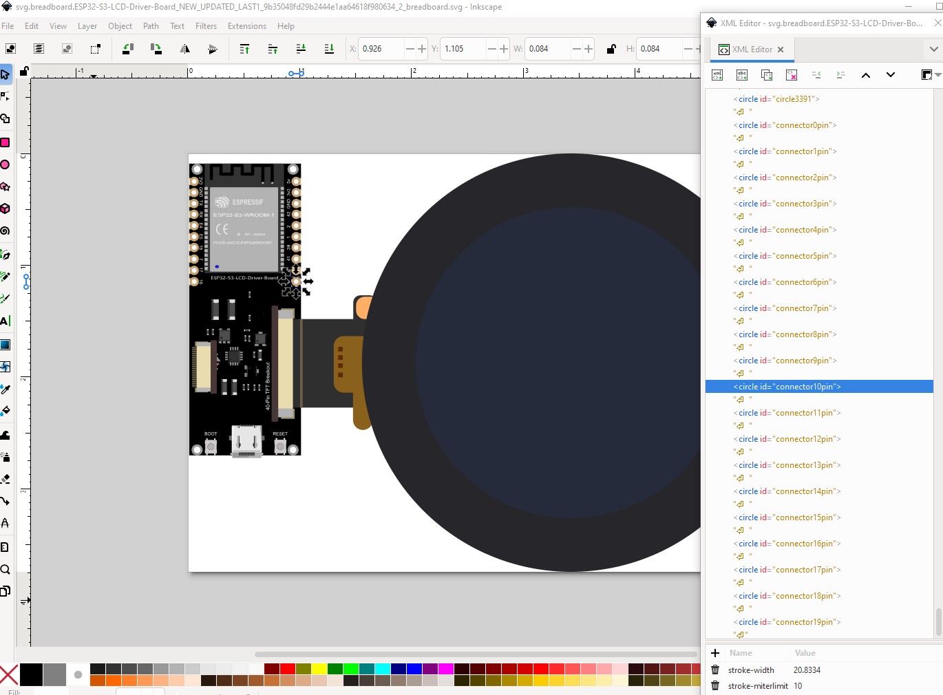
Your pins are also in the wrong order so we will correct that on the way by. Connector 10 needs to be the bottom right pin not the top right.
So move that to the bottom of the svg then do the rest in order from there.
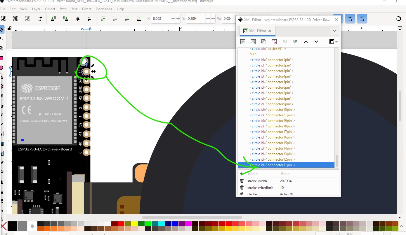
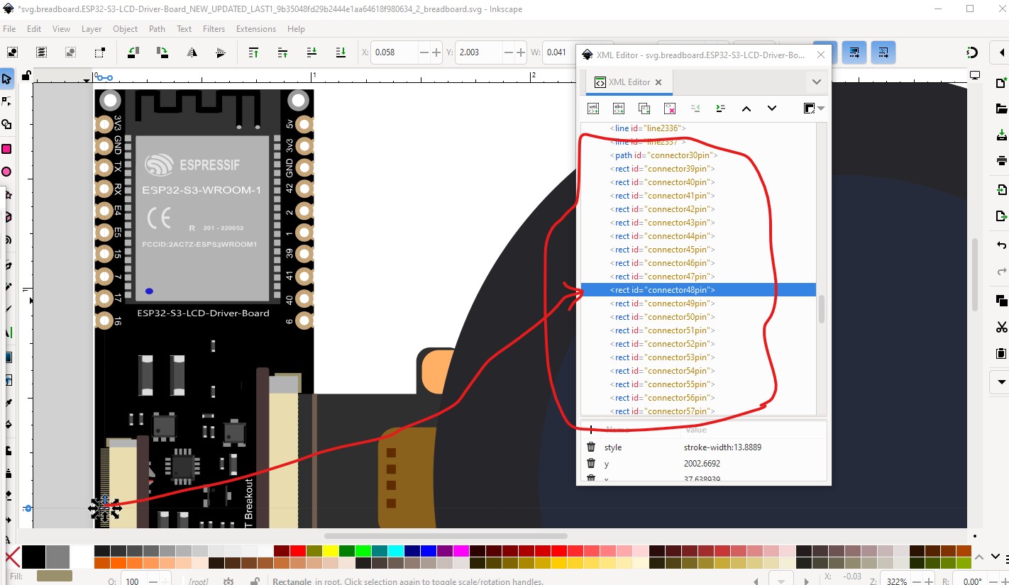
Now we need to correct the pin numbering while renaming the unused pins (of which there are a lot!)
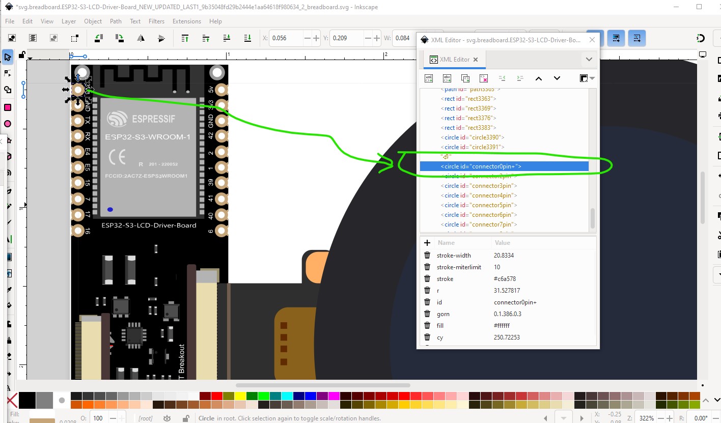
Now change the id of the new connector0pin to connector0pin+ which the script will recognize as where it is supposed to start (it actually screwed up and I had to rename the various connector0s to get it to work correctly.) Then run the script
$E2fRemoveUnusedConnectors.py svg.breadboard.ESP32-S3-LCD-Driver-Board_NEW_UPDATED_LAST1_9b35048fd29b2444e1aa64618f980634_2_breadboard.svg
which produces this output (and a corrected svg)
…
line 13284 connector ‘connector76pin-2’ deleted as unused.
line 13292 connector ‘connector77pin-2’ deleted as unused.
line 13300 connector ‘connector78pin-2’ deleted as unused.
line 13308 connector ‘connector79pin-2’ deleted as unused.
line 13316 connector ‘connector80pin-2’ deleted as unused.
line 13997 connector ‘connector0pin+’ changed to ‘connector0pin’.
line 14006 connector ‘connector2pin’ changed to ‘connector1pin’.
line 14015 connector ‘connector3pin’ changed to ‘connector2pin’.
line 14024 connector ‘connector4pin’ changed to ‘connector3pin’.
line 14033 connector ‘connector5pin’ changed to ‘connector4pin’.
line 14042 connector ‘connector6pin’ changed to ‘connector5pin’.
line 14051 connector ‘connector7pin’ changed to ‘connector6pin’.
line 14060 connector ‘connector8pin’ changed to ‘connector7pin’.
line 14069 connector ‘connector9pin’ changed to ‘connector8pin’.
line 14078 connector ‘connector10pin’ changed to ‘connector9pin’.
line 14087 connector ‘connector21pin’ changed to ‘connector10pin’.
line 14096 connector ‘connector19pin’ changed to ‘connector11pin’.
line 14105 connector ‘connector18pin’ changed to ‘connector12pin’.
line 14114 connector ‘connector17pin’ changed to ‘connector13pin’.
line 14123 connector ‘connector16pin’ changed to ‘connector14pin’.
line 14132 connector ‘connector15pin’ changed to ‘connector15pin’.
line 14141 connector ‘connector14pin’ changed to ‘connector16pin’.
line 14150 connector ‘connector13pin’ changed to ‘connector17pin’.
line 14159 connector ‘connector12pin’ changed to ‘connector18pin’.
line 14168 connector ‘connector11pin’ changed to ‘connector19pin’.
It renamed the unused connectors so they won’t cause confusion later and renumbered the connectors in order starting at connector0pin+
That fixes up breadboard. Now we need to do schematic and pcb svgs. Schematic had more problems (the text was paths which is undesirable) so I created a new schematic with Randy’ schematic Inkscape extension. Then I moved the pcb pins to the end of the svg in the correct order and set connector0pin Id to connector0pin, then ran the setbb.py script against pcb to renumber it correctly (on the way by I modified the pads to be standard 01.in header pads.) That completes the svgs. Now we need to correct the fzp file (which is where your main problem was) as Parts editor can’t correct the .fzp file you need to do it with a text editor (or in my case a text editor and a script to generate the new connectors.) Once that is one I needed to add the description fields to the template (which has no descriptions by default) via a text editor to match the labels in schematic. Then I needed to delete the incorrect bus definitions and define new ones for 3V3 and GND. with that done the new part was run through FritzingCheckPart.py to check for errors and the new part created and tested. I didn’t change the moduleId of this part so if you have the original loaded in your mine parts bin you will need to delete it and shutdown Fritzing (answering yes to save parts and save parts bin!) to really delete it before you can load this part which should do what you want.
ESP32-S3-RGB-LCD-DRIVER-BOARD-WROOM-1-N8R8_UPDATED.fzpz (100.8 KB)
It would be a good bet to verify the pins are all correctly labeled as they have all changed from your original part and there may be errors.
Peter
Hi Peter, thank you so much for your support! Reading your post, I realized there were details I hadn’t noticed.
Parts making is complex and tends to bite without warning. Learning to make parts well takes a considerable amount of time. These two tutorials (which you may be aware of, they get posted here a lot ![]() ) may help and apply to current versions of Fritzing. It is also useful to be aware that parts editor was not finished when development stopped in 2016, and while development is now restarted, parts editor hasn’t been finished yet. FritzingCheckPart.py (which will check and correct your part for various errors and svg editor limitations that Fritzing doesn’t like) can help.
) may help and apply to current versions of Fritzing. It is also useful to be aware that parts editor was not finished when development stopped in 2016, and while development is now restarted, parts editor hasn’t been finished yet. FritzingCheckPart.py (which will check and correct your part for various errors and svg editor limitations that Fritzing doesn’t like) can help.
I lately learned there aren’t links to the videos in Old_Grey’s tutorial so you need to do a google search for the title and then they come up on YouTube.
Peter