DS3231 VCC Pin Fix

I need help to fix DS3231 file, also known as the ZS-042-RTC. I think this is a default/inbuilt part and is located in the AppData\Local\Programs\Fritzing\fritzing-parts\core folder and the file is called rtc_ds3231_breakout.fzp. Specifically need PCB help on this.
Picture1

Everything looks OK on the PCB view but when exported to GERBER, the VCC pin is just a large hole. No through pin, no solder point, just a hole:
Picture2

I can fix this by opening the Gerber text files and manually fixing. First the Drill.txt file, this is what the VCC pin looks like the drill file. It’s clearly massive in comparison to the other drill holes.
Picture3

Selecting the VCC hole in my Gerber viewer (Gerbv), right clicking the mouse and selecting display properties, I see (in the Messages tab) that the “Location” of this hole is 898.3, 1083.3:
Picture4

So, opening the Drill.txt file I see the following drill bit sizes:

T1C0.064972

T100C0.051083

T101C0.051056

And further on in the file I see:
Picture5

Here is the problem. X008983Y010833 is mentioned under the big drill bit, T1 and the smaller drill bit, T100.

T100

X008983Y010833

So I delete this line under T1, save the file and reload the layer and voila, the VCC drill hole is now the correct size:
Picture6

But there is more to do. Next, is the Copper Bottom layer. The position is the same, so in this file I’m looking for the same X00898Y01083 line. And I find it under “G54D11*” when all of the other copper bottom entries around it are in G54D10*.
Picture7

So, let’s change G54D11* to G54D10*, save the file and reload the layer. Again, that’s fixed the small copper bottom, making it the same size as the other entries.

Last one is Mask Bottom text file. Currently the mask for the VCC pin is smaller than the other entries (as it was above for the copper bottom layer):
Picture8

Looking for the same line, X00898Y01083, again I find it under “G54D11*”. I change this entry to G54D10*, as before and it’s fixed.

Now it all looks the same and I know my PCB will arrive with all the plated through holes in place.
Picture9

I’d like to fix this using Ink Scape (or other way) so that I don’t need to fix the Gerber files for this part every time I use it, but that is beyond me.

Now I’ve given you the long way to fix this part, I hope someone will exchange the knowledge and help me out by either fixing the default, built in DS3231 (ZS-042-RTC) file or, preferably, by telling me how to fix it, either by editing the file or using ink scape.

In summary, the VCC pin on this file needs corrected by altering the drill hole size, the bottom copper layer size and the bottom mask layer size.

Thanks.

These tutorial details how to make parts (which is what you want to do here)

Fixing the part in core parts would take a pull request on github to fix. Your easiest bet is to do this to get a copy of the part

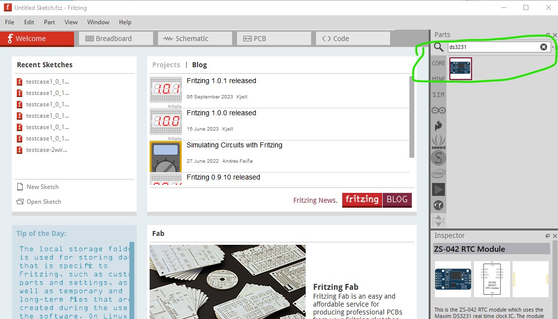
then right click on it and select Edit Part (new parts editor)
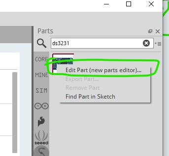
capture4

which gets you this

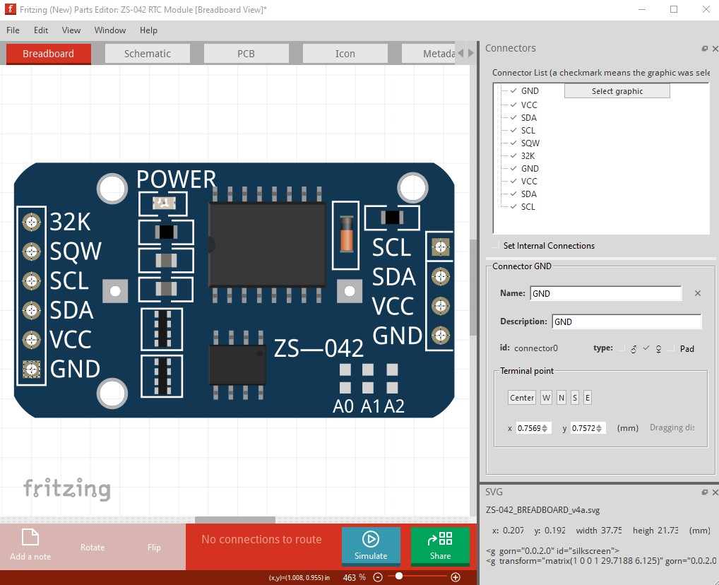
then File->save as new part and just click ok to the default prefix.

that makes a copy of the core part in your mine parts bin. Now you need to right click on that part and select export

capture7

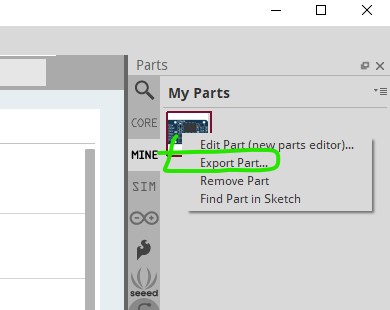
that will write a .fzpz file (you get to pick a name!) to the local file system. You then need to unzip that .fzpz file (which will produce a .fzp file and likely 4 svg files.) Using the instructions in either of the tutorials you then need to use Inkscape to edit the pcb svg and correct the pad definition, run it through FrtizingCheckPart.py to check it and then rezip the 5 files in to a .fzpz file. You can then use that .fzpz file as the correct part in your sketches (it will load in to your mine parts bin.) If you run in to problems just post, the procedure is complex and tends to bite without warning.

Peter

Thanks for that. I’ve never fully understood the parts editor (nor Ink Scape really) but I made a copy of the part had a look. All the XML that I could see seemed OK and the graphics all looked OK, which is pretty much where I was before I started changing the Gerber files.

I even opened the original part in WordPad and nothing stood out as incorrect or out of place.

However… I then exported the copy of the part as Gerber and had a look in Gerbv. Genuine big surprise - it’s fine! VCC connector, hole size, mask, etc are all the same size as the other pins.

So I’ll use my copy part from now but scratching my head as to why the original part doesn’t work, but making a copy of it fixes it. No matter, I’ll chalk it up to fairy magic and live with the fix :smiley:

Thanks again for the reply. Much appreciated.

That is odd. I’ll have a look at the part in core and see If I can see a problem (and if it does the same for me.)

edit:

The core part is indeed broken (it is already on my list of parts to fix in core) but for me exporting it via parts editor (on Fritzing 1.0.1) doesn’t fix it, the exported part is still broken. One hole is 0.064972in where the others are in the 0.051in range (and should be 0.038 for a 0.1in header!)

; NON-PLATED HOLES START AT T1
; THROUGH (PLATED) HOLES START AT T100
M48
INCH
T1C0.064972
T100C0.051056
T101C0.051083
%
T1
X002212Y014620
T100
X016111Y014777
X016111Y016778
X016111Y017777
X016111Y015777
T101
X002212Y018620
X002212Y017620
X002212Y015620
X002212Y013620
X002212Y016620
X002212Y014620
T00
M30

edit2

Since it is done, you may want to use this part

ZS-042 RTC Module.fzpz (16.0 KB)

In addition to the hole being 0.038in for 0.1in headers, the 3 mounting holes are in silkscreen. If you want the holes drilled you need to drag a hole in to the sketch then set the size appropriately (if the hole is in the part you need to modify the part to remove it.) It will likely take a while to get in to core parts (it was done in 2019 so has already taken a while …)

Peter

Thanks very much.

I double checked my original part and my copy part (that I did nothing with) and you can see the original on the bottom has the tell-tale greeny/yellow circle compared to the cyan of all the others. The copy part at the top is fine (Fritzing 0.9.9).

Anyway, I’ll delete the other parts now and use yours.

Thanks again Peter and apologies for accidentally jumping this to the top of your fix list.