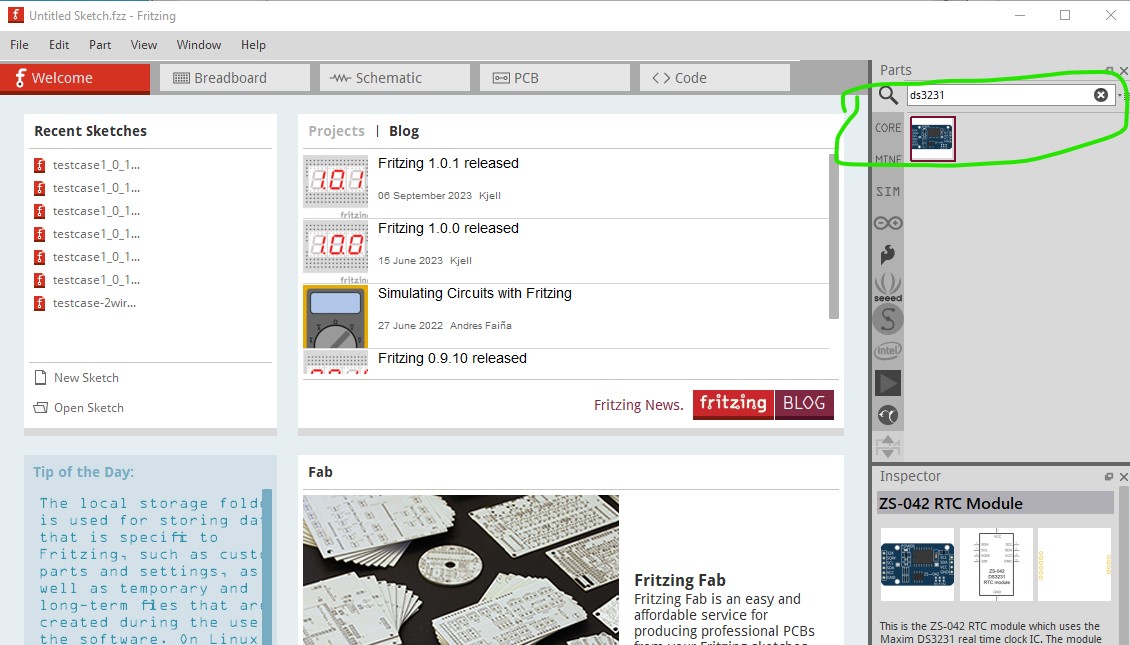
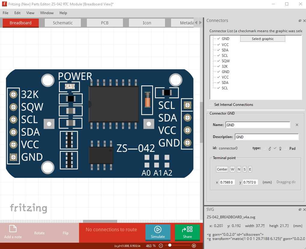
I need help to fix DS3231 file, also known as the ZS-042-RTC. I think this is a default/inbuilt part and is located in the AppData\Local\Programs\Fritzing\fritzing-parts\core folder and the file is called rtc_ds3231_breakout.fzp. Specifically need PCB help on this.
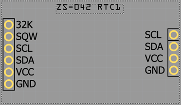
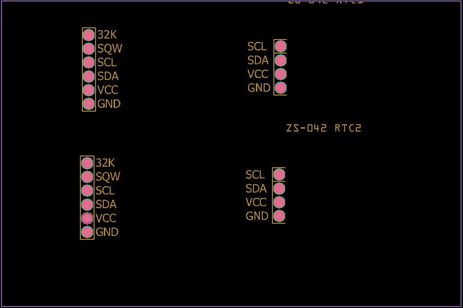
Everything looks OK on the PCB view but when exported to GERBER, the VCC pin is just a large hole. No through pin, no solder point, just a hole:

I can fix this by opening the Gerber text files and manually fixing. First the Drill.txt file, this is what the VCC pin looks like the drill file. It’s clearly massive in comparison to the other drill holes.

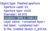
Selecting the VCC hole in my Gerber viewer (Gerbv), right clicking the mouse and selecting display properties, I see (in the Messages tab) that the “Location” of this hole is 898.3, 1083.3:
So, opening the Drill.txt file I see the following drill bit sizes:
T1C0.064972
T100C0.051083
T101C0.051056
And further on in the file I see:
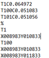
Here is the problem. X008983Y010833 is mentioned under the big drill bit, T1 and the smaller drill bit, T100.
T100
X008983Y010833
So I delete this line under T1, save the file and reload the layer and voila, the VCC drill hole is now the correct size:

But there is more to do. Next, is the Copper Bottom layer. The position is the same, so in this file I’m looking for the same X00898Y01083 line. And I find it under “G54D11*” when all of the other copper bottom entries around it are in G54D10*.
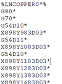
So, let’s change G54D11* to G54D10*, save the file and reload the layer. Again, that’s fixed the small copper bottom, making it the same size as the other entries.
Last one is Mask Bottom text file. Currently the mask for the VCC pin is smaller than the other entries (as it was above for the copper bottom layer):

Looking for the same line, X00898Y01083, again I find it under “G54D11*”. I change this entry to G54D10*, as before and it’s fixed.
Now it all looks the same and I know my PCB will arrive with all the plated through holes in place.

I’d like to fix this using Ink Scape (or other way) so that I don’t need to fix the Gerber files for this part every time I use it, but that is beyond me.
Now I’ve given you the long way to fix this part, I hope someone will exchange the knowledge and help me out by either fixing the default, built in DS3231 (ZS-042-RTC) file or, preferably, by telling me how to fix it, either by editing the file or using ink scape.
In summary, the VCC pin on this file needs corrected by altering the drill hole size, the bottom copper layer size and the bottom mask layer size.
Thanks.