how can i create custom shaped copper pad from a svg image. i am making a touch capacitive midi keyboard and need to create a bunch off copper piano key shaped pads.
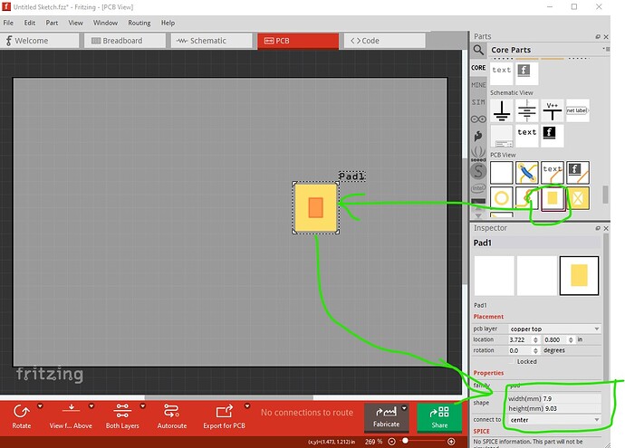
If you can use a rectangle the easiest is that pad in core parts / pcb
you can change the size in Inspector on the bottom right.
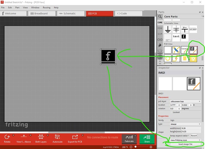
You can load an svg (but I think only in to silkscreen layer which isn’t what you want) with the icon image like this
otherwise you would need to create a custom part with the svg to put it on the copper layer (probably only one copper layer I expect so as an SMD part) which is a fair bit more complex.
Peter
ok so your saying import svg as a silkscreen layer. and convert to cooper? or just set it in as a silkscreen layer to have it there as a place holder image when it i etch the board.
Also how do I get to the editor screen , and make a part from scratch?
If you want a non rectangle as the image, then you need to make a custom part (which is quite complex.) It will probably be easiest if you upload your svg here (upload is 7th icon from the left in the reply menu) making sure the svg is dimensioned in “in” or “mm” (not px!) so the scale is real world, and I will make you a custom part. You should also indicate where you would like the connection to the part to be in the svg (it defaults to the center which likely isn’t where you want it.) It is easy for me, likely less so for you if you are new to part making. This tutorial will tell you what I am going to do (and usually discourages people from making parts ![]() ):
):
there are 11 or 12 parts to it.
Peter
so basically to make a part from scratch, i can’t start from scratch, it requires hacking a previously made part from the parts library on the right. and edit it to match what I am wanting to make?
are there any videos on youtube or anything of the process?
i saw this video on youtube. is this similar to your process? https://youtu.be/YhXBWQOn10k?si=xkAPyBibFQkA_drb
Not exactly. It is perfectly possible to make a part from scratch (I do it regularly.) To use the parts editor (which I rarely do) you are best to start from an existing part as it can not modify most parts of the .fzp file and needs to have a .fzp file which has the correct number of pins as a starting point. Part editor was not completed when development stopped in 2016 ( development restarted in 2019 but I believe the parts editor is still under development and a new one hasn’t been released yet. This tutorial is YouTube based and usually uses parts editor (and applies to current Frtizing versions which many of the others don’t):
I lately learned there aren’t links to the videos in Old_Grey’s tutorial so you need to do a google search for the title and then they come up on YouTube.
Your part should be reasonably simple (you need to start from an existing part which has 1 SMD connections though to get a correct fzp file with a SMD pcb file such as an SMD single pin header.)
Peter
Here is a way to get the part you want suitable for use via parts editor.
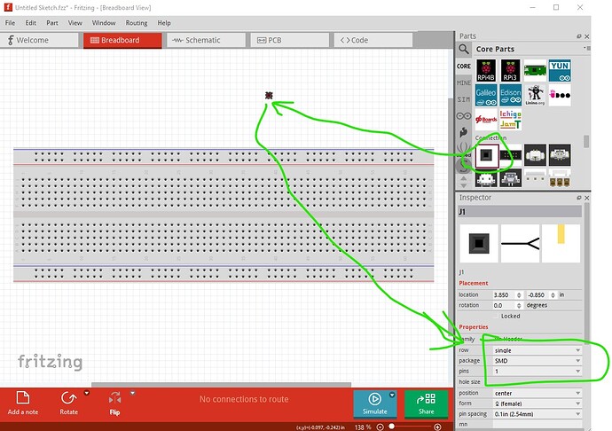
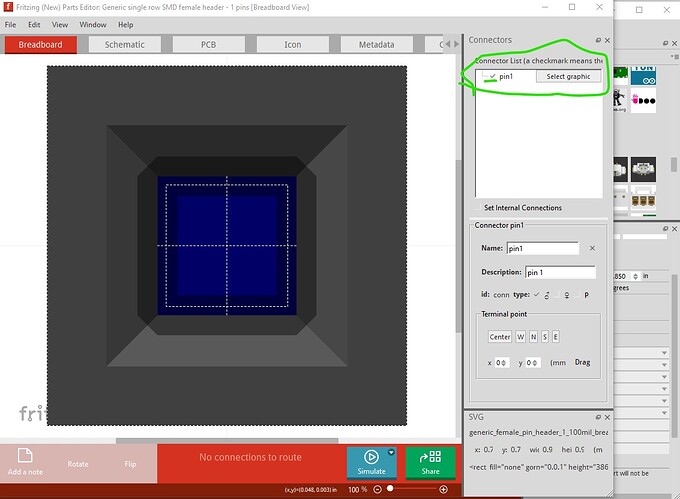
Make a single pin SMD header connector like this
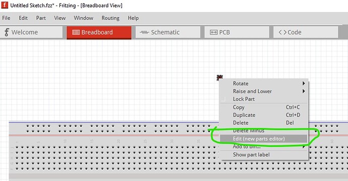
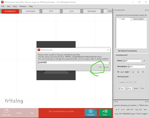
drag it in to a sketch then use Inspector to set it to 1 pin (from the defatult 2) SMD. Once that is done edit it with the new parts editor and save it as a new part by right clicking on the connector in the sketch
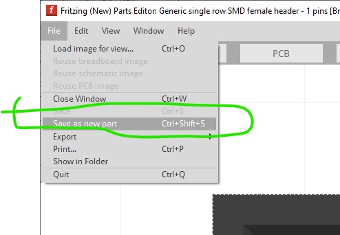
save it as a new part (accept the default prefix value is fine.)
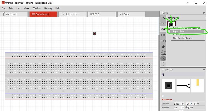
right click on the part in the mine parts bin and select export part to create an .fzpz file. Save the .fzpz file somewhere in the file system and then unzip the .fzpz file to get the .fzp file and the associated svg files.
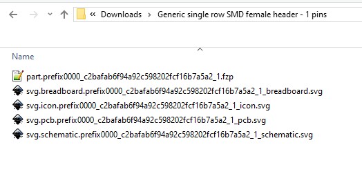
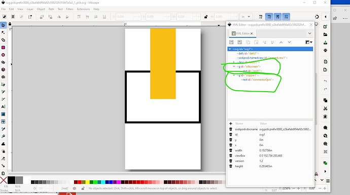
Now you need to modify your svg file to match the pcb svg file here (with a silkscreen and copper1 group.) You can then load that svg in to the parts editor and save the new part and you should be away.
Peter
oh cool. thanks for the screen shots. this will be extremely helpful. i’m gonna try it out after work. thanks so much
where do I load the svg after modifying in inkscape?
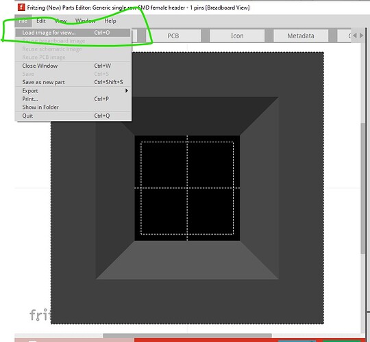
With a single pin header edited in parts editor, the load Image for view option it the file menu should successfully load your modified svg.
I think you may then need to set the connector if the box isn’t ticked (which it may not be after the svg is loaded, I don’t use parts editor a lot.)
That likely needs to be done for all three views as all three views must have the connector defined.
Peter
so when i export part and save as .fzpz it is compressed. and if i compress and then extract files. it just comes back to the same .fzpz file
Yes, if you uncompress the .fzpz it produces the .fzp and svg files, recompressing then reforms the .fzpz file. If you edit svgs you need to either run FritzingCheckPart.py or manually remove the px that the svg editor adds to the font-size values or Fritzing will likely screw up the font sizes.
Peter
so the one pin header in that format says it’s is compressed but when i right click. there is no uncompressed option. should i be exporting out of fritzing a different way? or is there a certain uncompressed program i need to add to my computer. im in windows 11
Any unzip program should work is is a standard zip file. I use 7zip on windows 10 which is an open source free version and works fine. I expect the built in zip program in Windows should work although I have never tried it.
Peter
It “is” a zip file, but some tools my not recognize it because it ends in “.fzpz” instead of “.zip”. Try renaming to end in .zip. You may first need to change the settings to show the file type.
rename the file type to .zip. how do i do that?
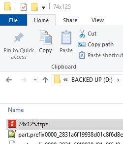
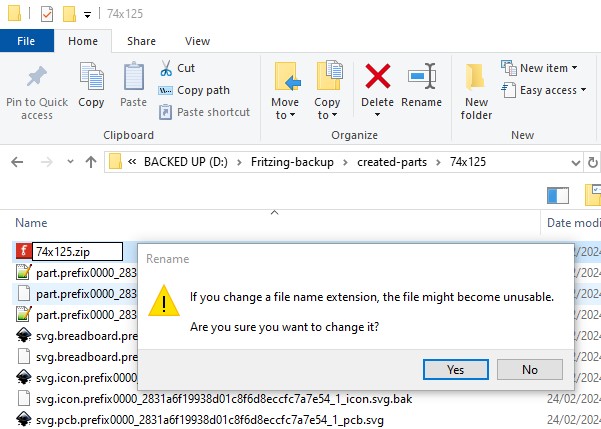
answer yes to make the change.
If you don’t see the .fzpz ending (which by default in Windows you won’t) you need to set show hidden file extensions in the explorer options page. 7zip will accept the .fzpz file and unzip it without the change.
Peter
thanks i’ll give 7zip a try. after work.
so after
it is unzipped. do i import all svgs into inscape? edit and add or subtract other svg to get the image im looking for. but then what. do i export all svg out of inkscape? or only the changed svgs?
also i really do appreciate your continued patience and help. I feel like i am so close to cracking this parts creation process lol
