I’m creating the images for the parts in inkscape,
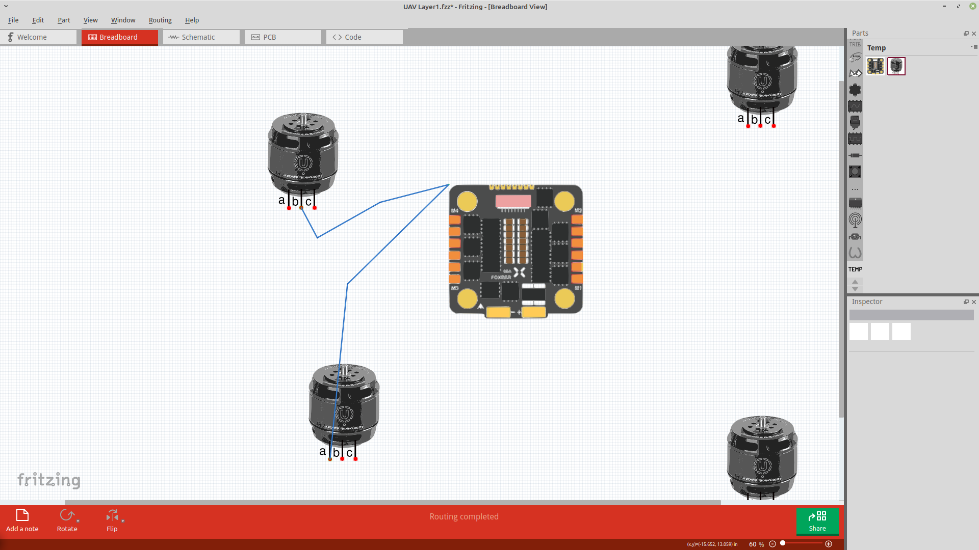
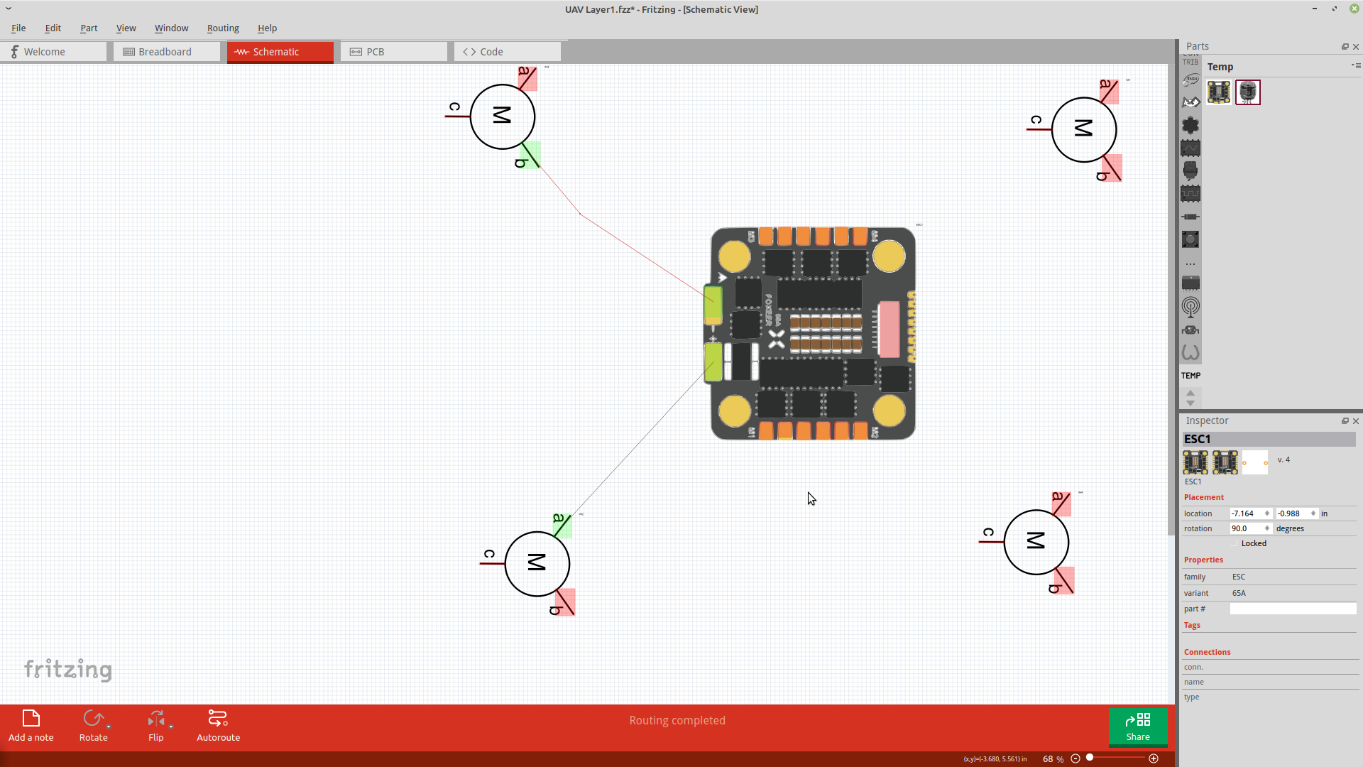
I have (for now) reused the same image in Breadboard and Schematic view (I only really care about breadboard view)
In the parts editor all of the pin graphics are selected in both breadboard and schematic views in a way that looks correct in the parts editor
When using the part in fritzing, the breadboard view has two pads that cannot be selected (there’s no red/green square on them), and any connections that go to those pins goes to the corner of the part graphic.
I have had similar issues with most of the parts I’ve tried to make so far.
While I obviously would like this specific case to be fixed, i mostly want to know what causes these issues in general and how to avoid them.
Thanks!
Woody
I tried to attach screenshots to show the issue, but only allowed one attachment, heres the part I created:
hmm, thanks Peter, I actually don’t know where .fzpz files are kept? I can only see .fpz ones in parts folder.
On plus side, I think I have just now solved the problem…
The two pins that weren’t working were the ones that were in the original part that i started with (only an issue because there’s no option to create one from blank canvas)
To solve the problem I deleted everything that was in the original part, creating a blank template and then started to build from there. I’ve realised that the most important part of that process was deleting all the original connections.
For some reason the connections on the new part do not function in Breadboard view unless they are deleted and recreated. In the other views they work fine either way.
Easiest is to right click on the part in the mine parts bin and select export part. That will write the part (the .fzp file and the 4 svg files) to a .fzpz file. Your likely problem was pins defined in the .fzp file that didn’t exist in the breadboard svg file which will cause problems.
While it is easiest to start from an existing part (required in parts editor because it can’t create the complete set of files) it is possible to make a part from scratch if you know the file formats well enough. These two sets of tutorials on making parts apply to the current versions of Fritzing (most of the rest are for previous versions, pre parts editor.) The videos cover parts editor I think, I don’t use it that often so mostly ignored it.