I’m new to Fritzing and thought it would be a good way to visualize moving my projects from the breadboard to perfboard. I don’t really care too much about simulating the circuits as I know they work already. Drawing them out on graph paper was fine but I thought rearranging components via Fritzing would make the whole thing neater and faster.
That being said of course I have parts that don’t match what is offered. I found a few googling but I thought I could easily create ones I could not find. The parts editor said to use Inkscape and GIMP which I already used for work so I thought it would be easy. I cant seem to
Why can’t I just input the package size and location of the pins? I looked for similar parts in the bin but could not find one where i could edit the size and/or number of pins.
Because that isn’t how parts are created and because parts editor is not finished (and is thus limited.) If you really want to make parts (which is quite difficult) these two tutorials apply to current Fritzing versions and we are happy to provide assistance if you have problems. For perf board you are looking for top view parts (which are modified for use on perf board.) A google search of the form “fritzing part part number top view” (where part number is the name of the part you want.) will find anything available. Here are the pointers to the tutorials:
I lately learned there aren’t links to the videos in Old_Grey’s tutorial so you need to do a google search for the title and then they come up on YouTube.
Creating fully custom parts is more difficult than it need to be.
In many cases there could be a simpler way though, depending on what parts you need.
There are some generic parts that can be customized (e.g number of pins and names).
And there are already a lot of footprints / packages, editing those is easier than creating from scratch.
What kind of parts or packages are you looking for?
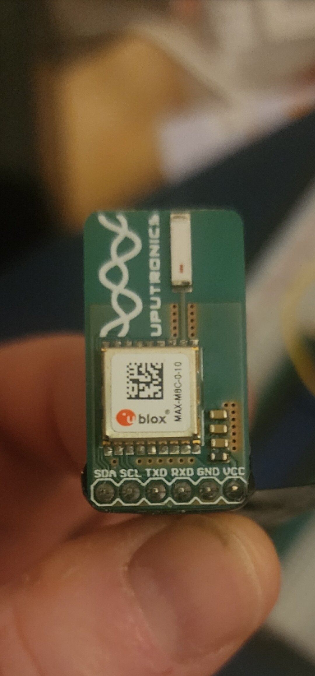
Just this gps breakout module. Should be simple. I’m just interested in the pins and form factor. I’m not going to simulate anything I just want to be able to arrange and rearrange on the computer so when I lay it out on the perf board it’ll be pretty organized.
If you have the web site for the part and you post it in the parts help category I (or one of the other parts makers) will make the part for you . If you only need a small number it probably isn’t worth learning parts making because as noted it is complex. I need the physical dimensions of the board and the location and names of the pins for the connectors (and preferably a flat jpeg image of the board to place the components and text) to make a part.
I do already know inkscape and Gimp So hopefully that’ll be enough for me to try.
If it ends up taking me forever is just too confusing I’ll post that part in the way that you asked me.
Thanks much. It’s awesome that there are people like you out there helping people like me.
If you are using parts editor you need to start from a part with the correct number of pins (looks to be 6 in this case.) A 6 pin header would be a good bet in this case. That will provide you with the fzp file with the correct number of pins (parts editor can not currently modify the number of pins in the fzp.) It is a good bet to run your completed part through FritzingCheckPart.py (detailed in my tutorial) as it both checks for correctness and removes some of the elements Inkscape adds that Fritzing doesn’t like (such as px in font sizes.)