Attached an updated and extended Cherry MY Blue key switch inc. outline of 18mm key cap.
The technical information is available here:
https://www.cherrymx.de/en/dev.html
Cherry MX Blue.fzpz (7.3 KB)
Attached an updated and extended Cherry MY Blue key switch inc. outline of 18mm key cap.
The technical information is available here:
https://www.cherrymx.de/en/dev.html
Cherry MX Blue.fzpz (7.3 KB)
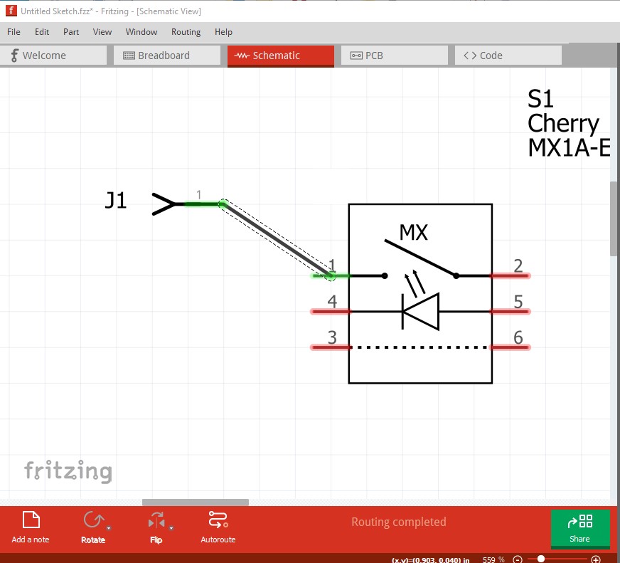
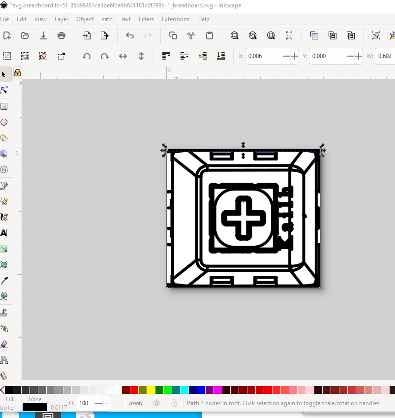
Your part has a number of problems. The svgs are dimensioned in px which makes them difficult to edit (they should be dimensioned in in or mm to avoid problems.) Schematic lacks terminalIds and thus isn’t aligned to the 0.1in grid as it should be
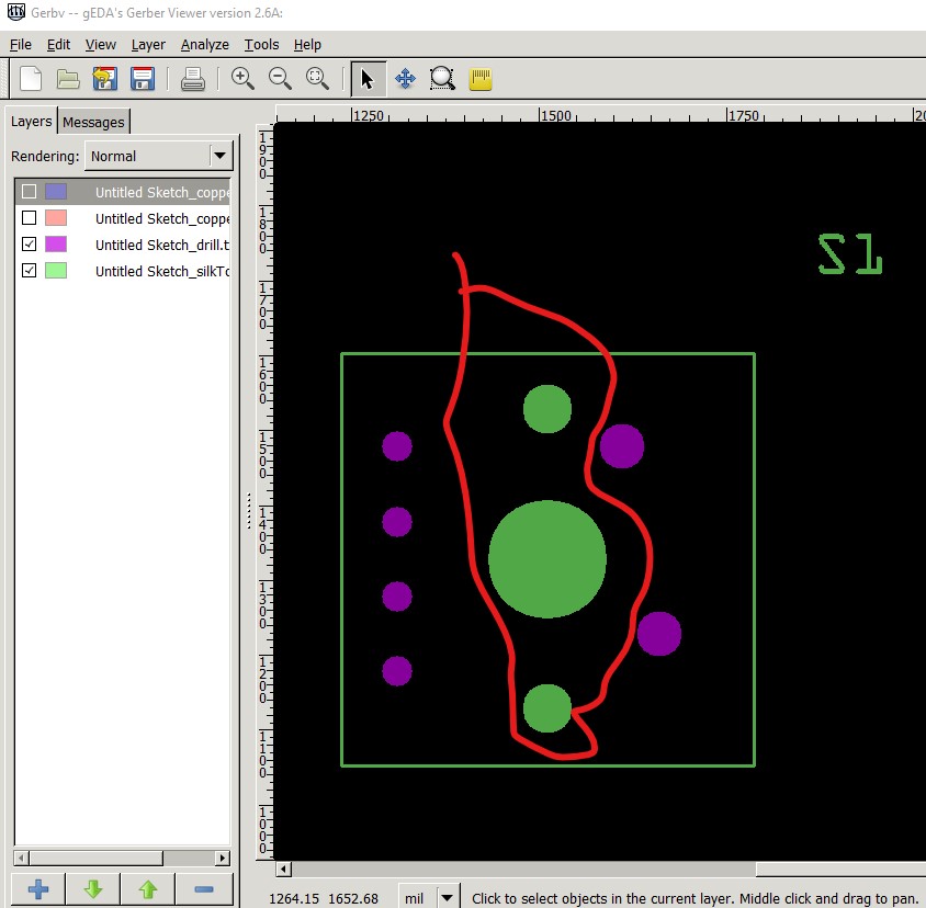
note that the wire connects to the center of the pin (which is aligned to the grid) rather than the end as it should. Pcb is not drilling the mounting holes when I expect it should be as they are needed. That may be a feature as you can drag the hole part in to the sketch to add the holes.
the holes outlined in red will not be drilled.
Peter
On the end found a lot of hints in the beginner section (a link to this on the web page would help many others)…
Attached the updated version ;-)).
Cherry MX Blue.fzpz (7.4 KB)
Still many problems. If I didn’t mention it before, this set of tutorials apply to the current version of Fritzing and should help:
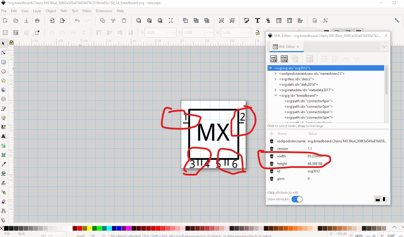
That said breadboard (all the svgs in fact) is still dimensioned in px which is incorrect and will cause problems. As well the breadboard view isn’t typical it should look more like this:

This is a breadboard svg file. Right click on the image and click save image as to download it.
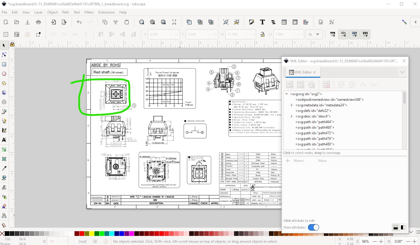
which is an image extracted from a pdf data sheet. I can’t find a proper data sheet for the MX blue part (the above was taken from a red here
this is your original breadboard. The pins should align to the 0.1in grid and do not. As noted before the dimensions should be in in or mm and should have a viewbox.
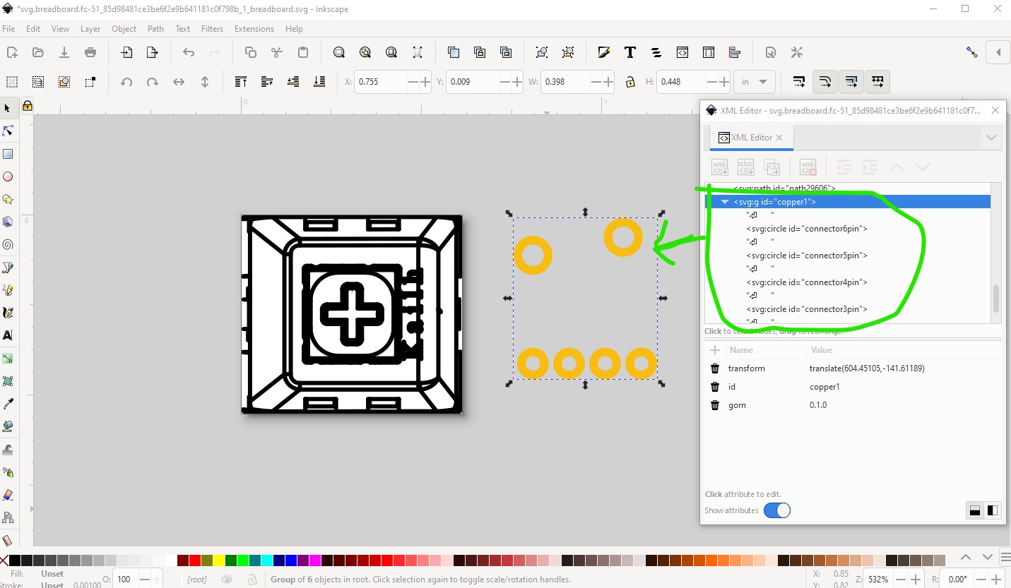
So import page1 of the pdf data sheet and ungroup it. Use the circled in green part for the new breadboard symbol.
copy in the connectors from the pcb svg and set them to be invisible.
then move them over the image to be in the correct place.
Without a datasheet for the actual part I didn’t do anything about schematic of pcb. Hope this helps.
Peter
Hi Peter,
thanks a lot for all the links an hints ;-)). There is an incredible amount of information in the forum, I am impressed! This helped to update the part to a shiny one (in my view)…
Cherry MX Blue.fzpz (6.5 KB)
The best spec I could find is here: Cherry MX Spec (mouser.com)
That data sheet (like the others I found) only shows 4 connections not 6 as your part has. It isn’t clear to me what the final two pins are supposed to do, they show as a short in schematic which seems pointless.
Peter
Hi Peter, in the spec are 6 sub types listed (second last letter of the MPN)
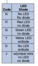
The layout of this options (LED, diode) is shown here:
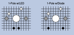
Therefore the LED is pin 4+5, diode/jumper wire would be 3+6.