My bread boarding requires a Generic 3-Row pin header, with 0.1" pin spacing, and 15 pins per row.
I have not been able to create same using the Parts Editor.
Can someone help me with this?
My bread boarding requires a Generic 3-Row pin header, with 0.1" pin spacing, and 15 pins per row.
I have not been able to create same using the Parts Editor.
Can someone help me with this?
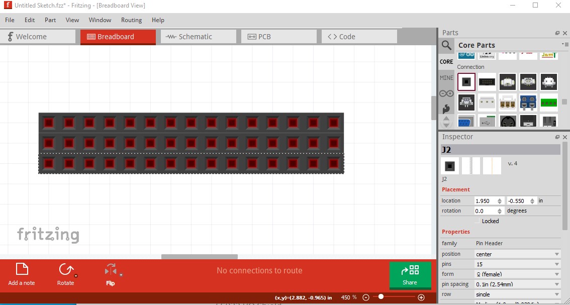
The easiest solution is to drag three single row 15 headers in to breadboard like this:
Change the gender to male if you need male pins. A custom part is more difficult and usually not worth the effort unless you are using a lot of them (in which case we would need to know if you want male or female pins to make a part.) You also need to move the pins to the correct places in schematic and pcb (unlike a custom part.)
Peter
Thank you Peter. That’s what I thought. I was just hoping that I could make a 3-Row custom part in order to make a shield of my own for my 30-Pin ESP32 Dev Module.
It is easy enough for me to make a custom part (probably less so for you  ), do you want male or female (or both) pins?
Peter
Peter:
I would prefer a 3-row pin-pin header with 15-pins/row
Thank you!
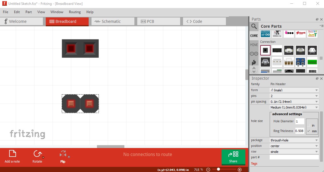
Peter: pin-pin header is male pin-male pin. I want this 3-row header to plug into the PCB. I will then connect to the topside pins using a jumper wire with a socket end.
Ah! OK you want male pins (the bottom side being male is implied a female header has an implied male pin on the bottom to connect to the pcb!) I`ll make a part in a bit.
Peter
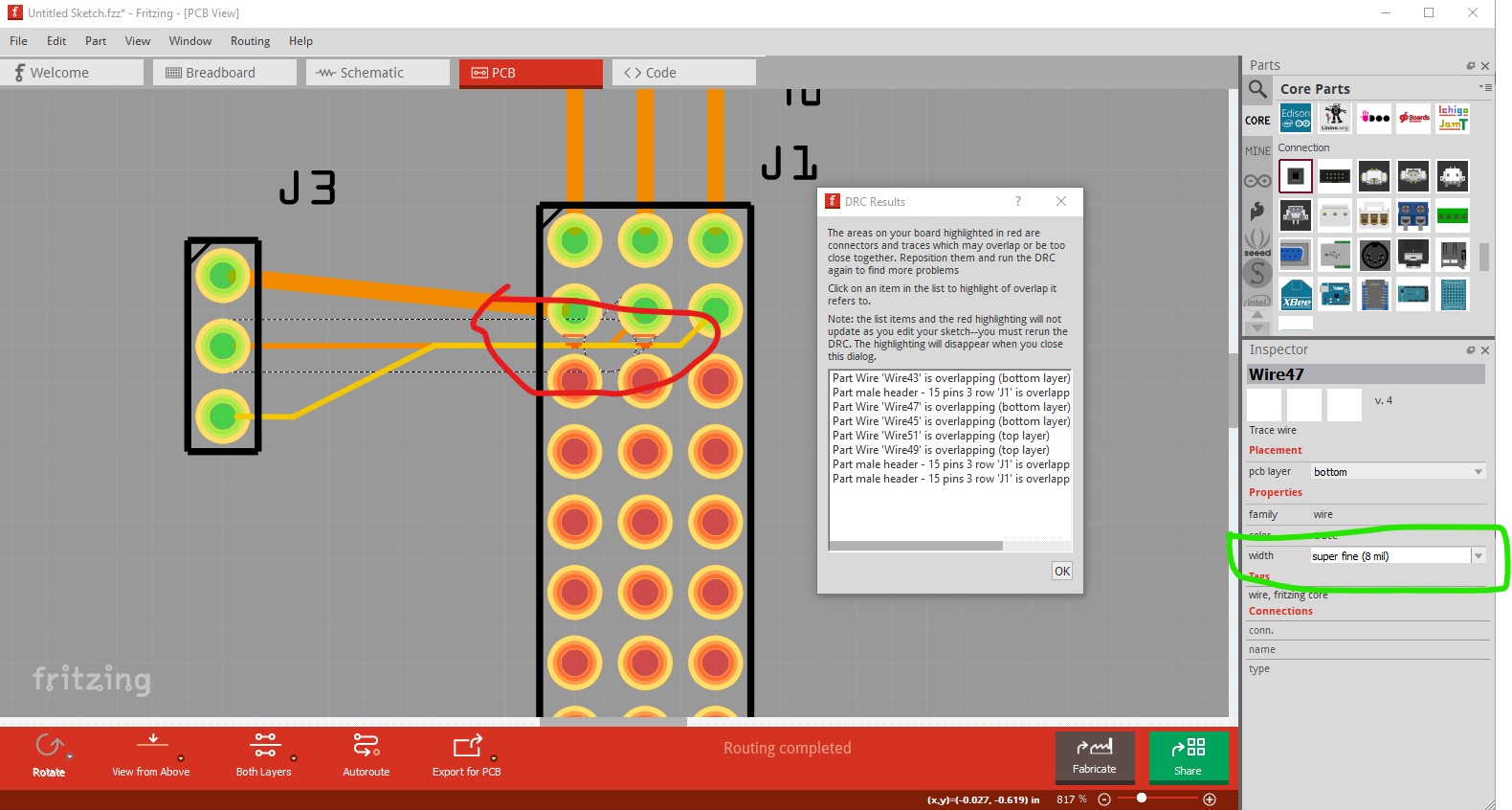
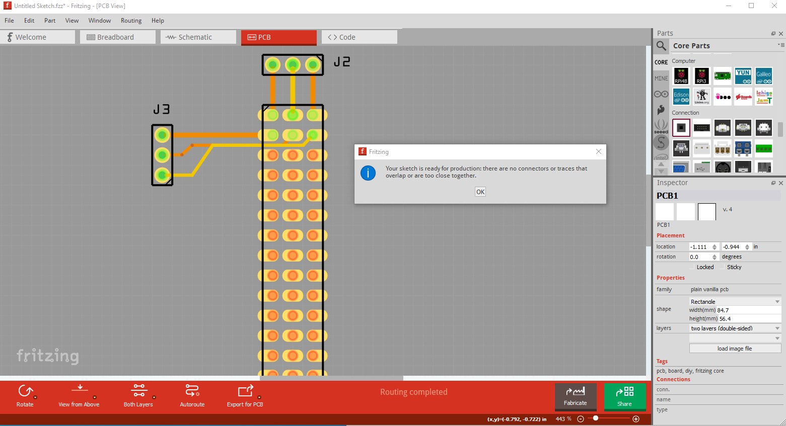
OK here is a new part. Turns out I was wrong, you probably couldn’t make this easily the third row causes an issue in pcb:
even with the finest (8mil) traces DRC won’t pass to run wires in to the middle pin. Luckily I had already solved this issue for a RaspberryPI GPIO connector and can use the same bits here:
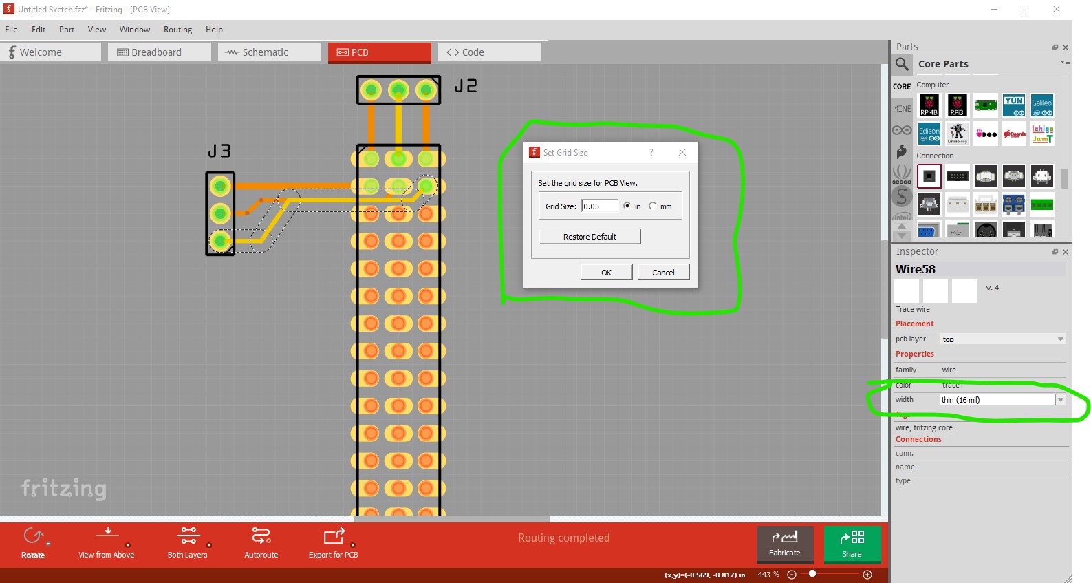
Note in both cases I needed to set the grid size to 0.05in from the default 0.1in to get the wires routed between the pins. On the final part with 16mil traces default DRC passes:
and finally the part:
male-header-15-pins-3row.fzpz (12.5 KB)
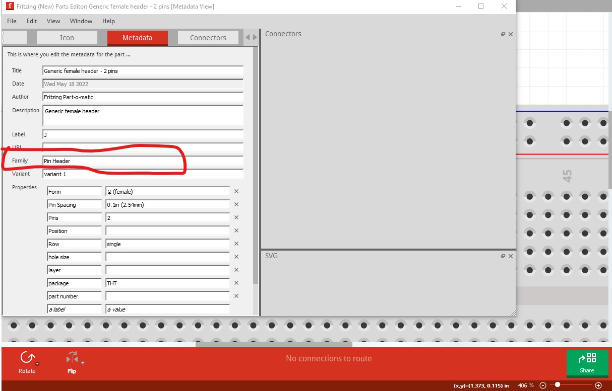
I’ll note in passing, if making new parts from any of headers, the generic IC or the mystery part it is vital to change the family name in the .fzp file (or in the metadata in the Parts editor) because the standard family name will trip internal processing and allow Inspector to modify your part with unfortunate results.
Peter
Thank you Peter! Yes, I ran into this same problem from which I learned some new “words”, as I tried to work thru this issue several times. I appreciate your talents which you relied upon to make this part.
I do have a selfish type of question. Can I take this part from my parts bin and by adding rows thru editing, create a new part with say, 18, 3-pin rows to suit a new breadboard design requirement?
Thank you once more for the help in creating this 3-row pin header Fritzing part.
You should be able to. If you unzip the .fzpz file you will get a set of files like this:
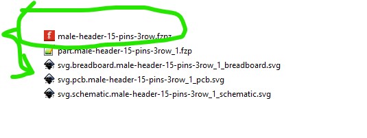
the .fzp and 3 svg files are in the zipped in the fzp. You can then edit the various svgs and use copy and paste in Inkscape (duplicate works but loses connector names which I usually want to keep.) I usually work from here and ignore parts manager. Your best bet may be to make a generic header with the same number of total pins as the new connector you want and edit that with parts editor (it has to have the correct number of pins because parts editor can not currently add pins to the .fzp file, only use what is already there. As noted it is important to change this field to something other than Pin Header:
to avoid Inspector thinking it is a generic header and it can therefore manipulate it. I used male-3row-15pin as the family name (it must be unique in Fritzing as well so you can’t reuse that one ![]() !) Now you need to use Inkscape to edit the svg files (breadboard, schematic and pcb) to add the images and connectors for the new part, then either use Parts editor to set the names and locations of the new connectors visually or do it by editing the .fzp file with a text editor (which requires you to understand what the xml in it does, the parts editor may be easier!) Inkscape also does things that Fritzing doesn’t like (the main one is appending px to text font-size for CSS compliance, Fritzing wants the font-size with no trailing px and will some times set the font size to 0 (or sometimes max) making the text the wrong size. You can either edit the svgs post Inkscape to remove the px in the font sizes or (as I do) run FritzingCheckPart.py available here:
!) Now you need to use Inkscape to edit the svg files (breadboard, schematic and pcb) to add the images and connectors for the new part, then either use Parts editor to set the names and locations of the new connectors visually or do it by editing the .fzp file with a text editor (which requires you to understand what the xml in it does, the parts editor may be easier!) Inkscape also does things that Fritzing doesn’t like (the main one is appending px to text font-size for CSS compliance, Fritzing wants the font-size with no trailing px and will some times set the font size to 0 (or sometimes max) making the text the wrong size. You can either edit the svgs post Inkscape to remove the px in the font sizes or (as I do) run FritzingCheckPart.py available here:
which will check the part for correctness and complain about errors (again requiring knowledge of the xml to fix usually!) and remove the px from font size and a few other things on the way by. So yes it is possible, it is just a bit complex. This set of tutorials may help.
both apply to the current version of Fritzing (many others are for older Fritzing versions.) Unfortunately Fritizng is full of poorly documented gotchas (like px in font size), I still run across lots of them.
Peter
Wow! Thank you for this information packet and the “how” to make it happen. This work and learning experience will keep me busy for some time.
The 3-Row pin header part works just fine. Thank you for all of the help extended with all of these postings.