A .fzz file is for a sketch, this is a part which is a .fzpz file, If you download the .fzpz file then in Fritzing do File->open->file.fzpz it will load the part in the the mine parts bin. You can then drag the socket in to a sketch just like any other part. When you save the sketch you will get a .fzz file (and the socket will be embedded in it, so that when someone else loads the .fzz file who does not have the socket part loaded, the sketch will still work.) At the moment I think I’d wait to see what @oemcar thinks of the latest attempt. The earlier ones have the pins to narrow because I misunderstood what the data sheet was saying about pin spacing. I think the latest 9 pin version is maybe right, but I don’t have a socket to check. Once we get a working footprint I’ll post correct copies of both the 9 and 10 pin versions.
Ahhh! Now I see what you mean. Yes, in the “mine” parts bin I see the socket.
If I then drag it into an existing pcb design of mine ( already a produced pcb), I notice that it does not have the correct size. Will look at it further and let you know! But now I can work this out for myself.
tube-socket-9pin-3.fzpz a couple of posts above should be correctly sized I think. It only has 9 pins, but that can easily be changed to 10 if you like.
Have imported the 9 pins socket and at first impression it seems OK but I have to print it out to compare it with the hardware version. That 10 pins version is too small I think.
Will respond on it as soon as possible (22:15 hrs local time here).
ps. is there a way to locate items by coordinates in fritzing? If not- thinking adjust the snap spacing on the grid to value integral with desired location points, and it should default to that spot if part dragged in close vicinity? Make sense?
Joe,
I printed an .svg export, which I think is 1:1 ratio. The pins location measured correct to the diagram I supplied Peter. The silkscreen looks to be 33mm diameter, not 25mm as the outer diameter of the socket diagram shows. This wont affect fitment, but if it was changed to 25mm, might help with layout.
Personally- I don’t need that outer silkscreen circle shown, but that’s just me.
Jim
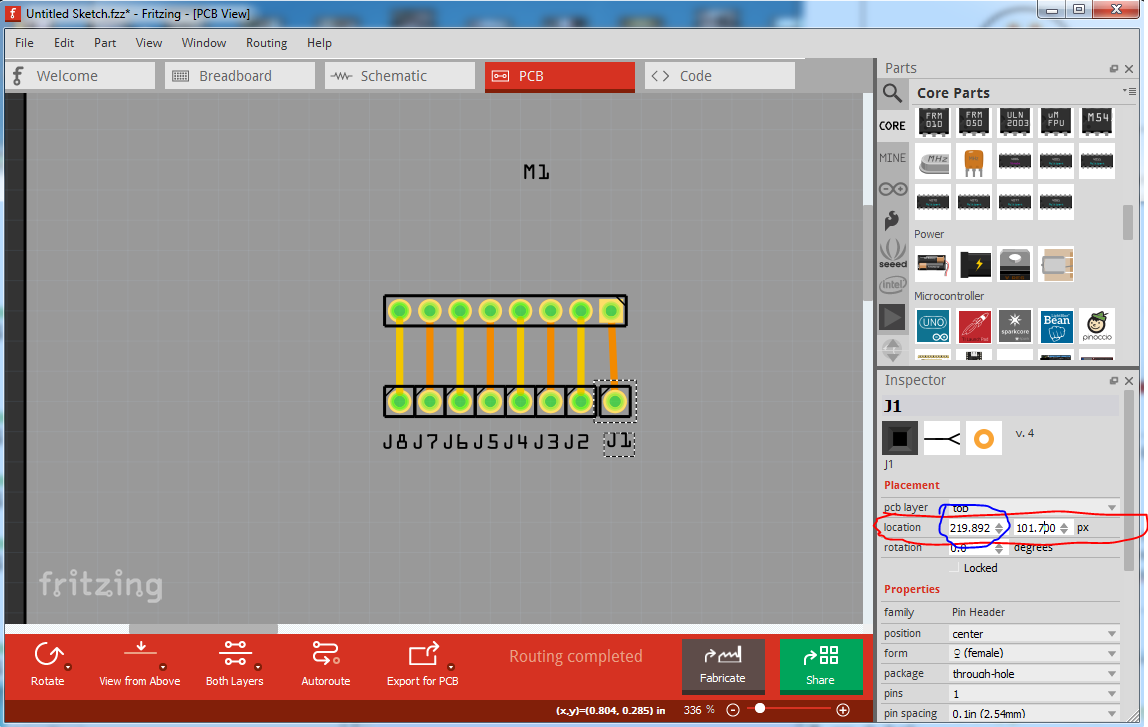
the “but” is that it has a funny idea of coordinates sometimes (it appears to be converting to some value system and sometimes has round off errors maybe or simply a bug.) So setting x (the left most coord circled in blue) to 219.800 here updates to 219.892 rather than the expected 219.800. I don’t know why, I think someone opened an issue on github about this though. The same happens in mm, but inches seems to work correctly for the values I tried although perhaps I just wasn’t low enough, 2.4 gives 2.400 but 2.401 gives 2.400 and 2.4.02 gives 24.04 which is less than useful so hopefully we can find and fix it.
I haven’t tried that, but it is worth at try. It may run in to the same conversion bug, or may not. If it doesn’t and puts parts in the correct place that may be a good work around for now.
Joe,
Just realized you can rotate each socket in the inspector in increments of 1*. So if use 36* shifts, you can put the #10 void wherever you want it.
Jim
OK, this should be a correct part with breadboard and schematic now reflecting PCB. If you want a 10 pin version, let me know, it is easy enough to add a 10th pin, but I think rotating this one with the key is the way to go.
Just printed out that “tube-socket-9pin.fzpz” file in fritzing and compared it with the hardware version : it fits perfectly !
And indeed there is no (more) need for a 10-pins version because of the “rotate” possibility which I completely have overlooked.
Thanks a lot you two !
Much appreciated!!
Sure, it should be an interesting challange I need to find a way to get the angles for the pins, but I think with lines and rotate in Inkscape it should be doable. I’ll give it a shot.
Thanks in advance Peter.
I find my way using Inkscape in a reasonable manner, so
how can I, when also having a prototype “.svg” version convert this into that “.fzpz” file?
Have not the foggiest idea, but I do not want to sit down, watch and doing nothing so…
Probably a look at this tutorial series will help:
I rarely use parts editor, preferring to edit the files directly. A .fzpz file is really a zip file. You can use 7zip (an open source unzip) or probably any zip program to unzip a .fzpz file. That will give you a .fzp file and 3 or 4 (depending on whether there is an icon svg) svg files in a format like this:
contains the .fzp and 3 (in this case no icon, as I reused breadboard) svg files. The funny part. and svg. prefixes are for the Fritzing loader who will store them in a series of directories like this (which is the format of the parts git repository):
core/
fzp-file.fzp (stripped of the part.)
svg/core/breadboard/
file-breadboard.svg (stripped of the leading svg.breadboard)
svg/core/pcb/
pcb.svg
svg/core/schematic/
schematic.svg
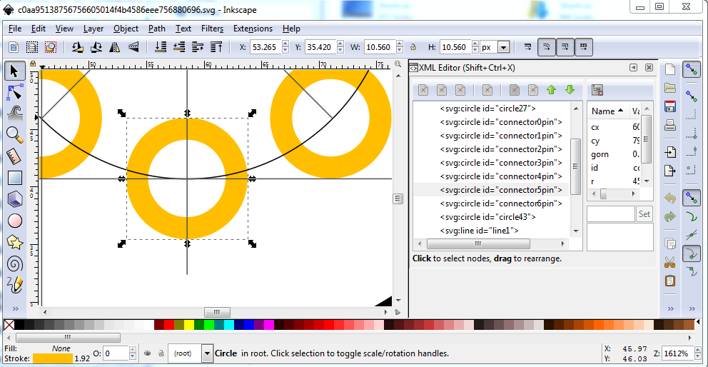
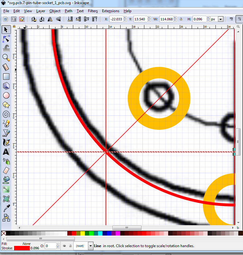
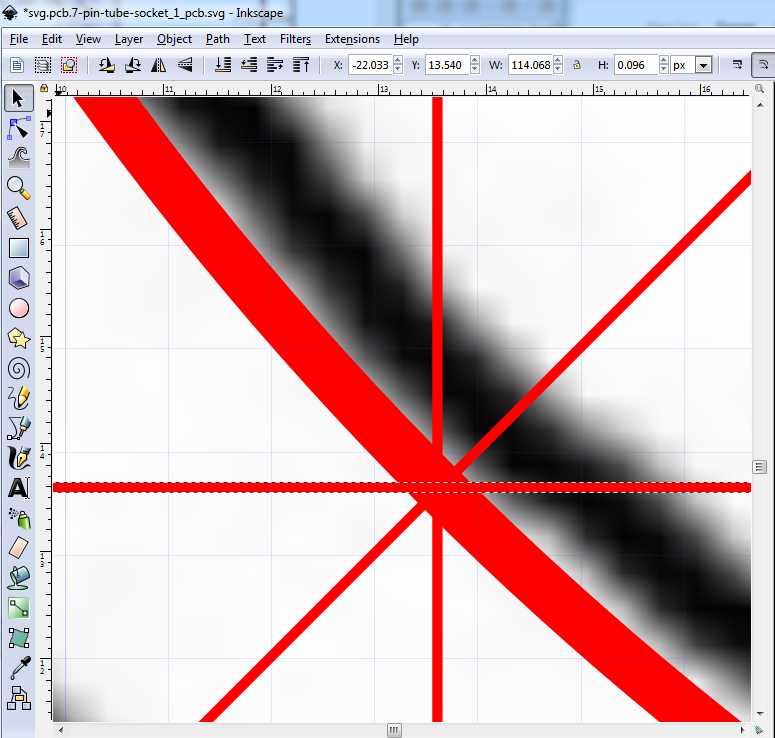
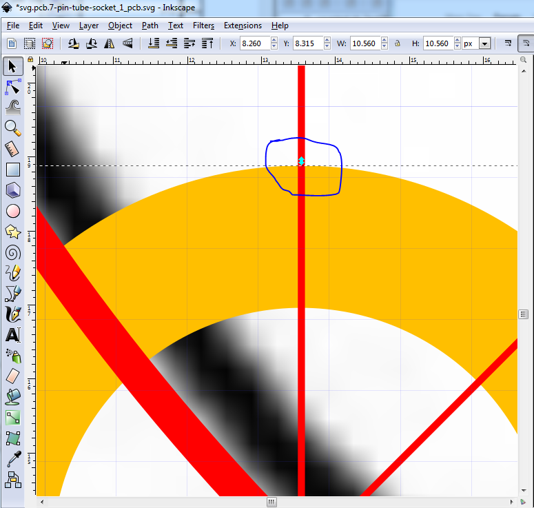
When you have done the editing, just rezip the fzp and the 3 svgs and rename the .zip file to .fzpz and Fritzing will happily load your changes. For the tube socket I’m fairly sure I can duplicate lines then use transform/rotate in Inkscape to get the angles, then add half the length of the line in X to center the rotated lines on the bounding circle. It will be fun to try, and I’ll document it for others assuming it works as I expect.
Edit:
That was easier than I expected. Here is a part, hopefully correct the holes are 0.07in in diameter the pins show as 1.7mm which is 0.066in so hopefully enough clearance, but the hole may need to be a bit bigger to fit properly.
reduce circle diameter to 18.6mm via dia to get radius then restore the diameter and change the radius to change the size of the circle without moving the center point (which changing the diameter does.)
duplicate the circle to make the pin circle at 9.5mm reduce the stroke width to 1 before resetting the radius (again set the diameter in the toolbar to get the proper radius, then back out the change and change the radius in xml editor.)
maka a stroke width 1 line 9.5mm long centered in the circle then duplicate it.
set y to the y value of the circle then adjust x til the line is in the center of the circle.
duplicate the line, then object->transform->rotate 45 degrees and apply.
dup the resulting line and rotate it 45 degrees
dup the resulting line and rotate it 45 degrees
We now have the points where the pads should be on the circle so move them in to position.
copy in a line twice, rotate one 90 degrees and line them both up to intersect the 45 degree line on the circle. Then adjust the x/y position of connector0pin to be on the lines.
holes of 0.07in reduce stroke-width to 20 so diam .11in radius 45
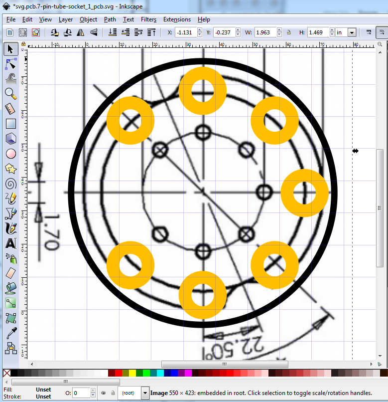
Below (forum willing ) is the pcb svg with the construction lines in place:
The forum (with the usual edit the px values to go from 1 to 1000px) was willing, so if you right click and “Save image as” on the svg above you should get the svg with the construction lines described above still in place. If you select connector5pin, you will see how the construction lines are used to position the pads.:
Peter,
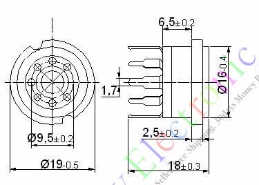
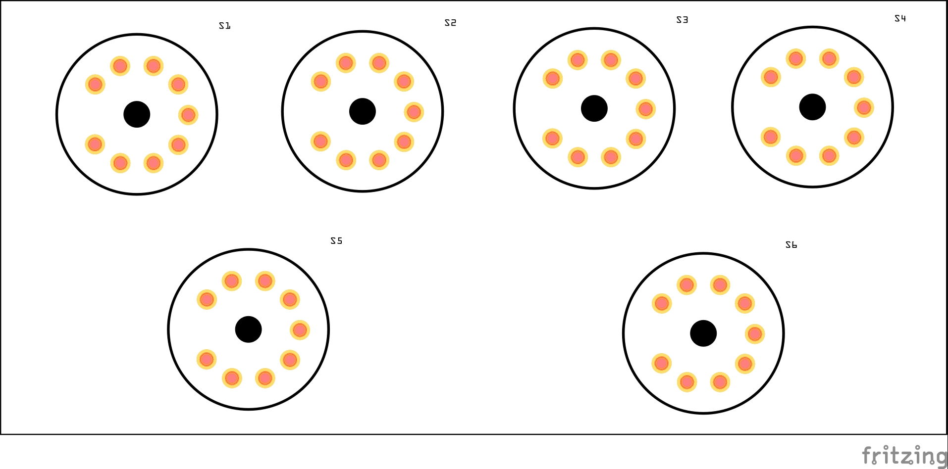
Looks like circular pattern used was the actual tube pins, not socket pins location-
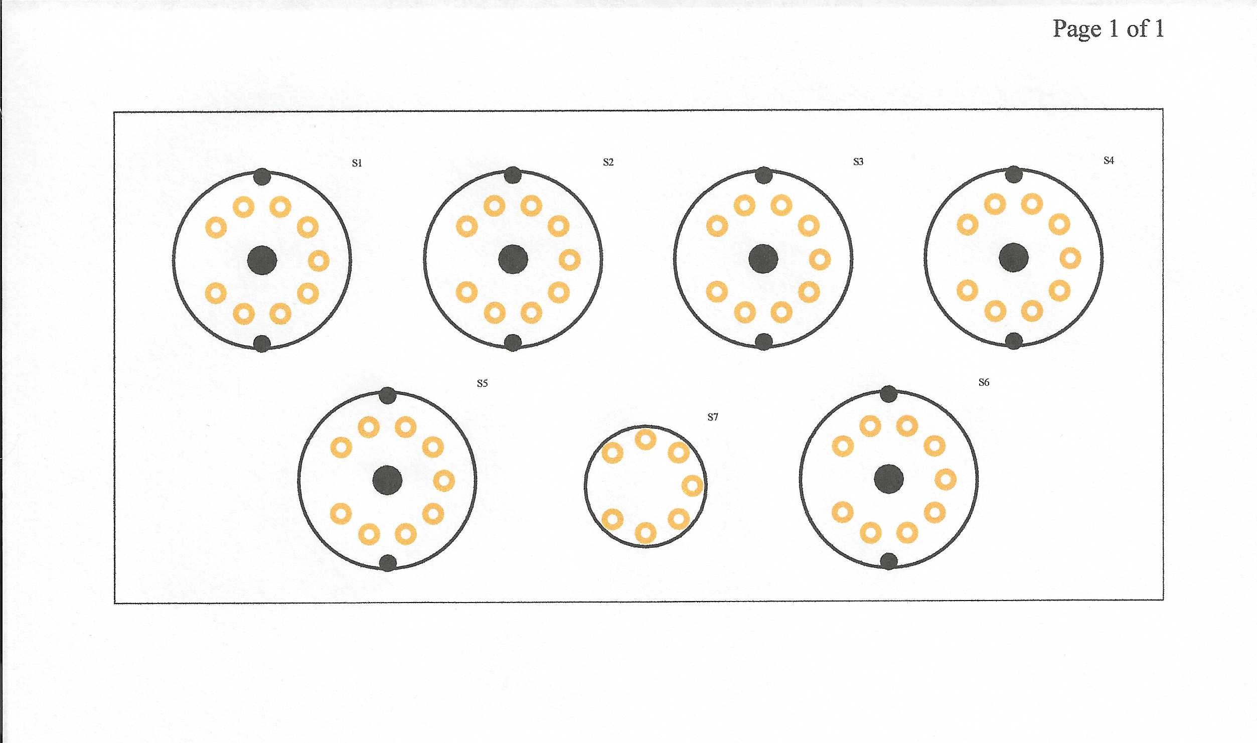
I’ve attached different diagram which suggests socket pins are on 16mm pattern instead of 9.5mm. I say ‘suggests’ cuz actual pins radial location aren’t spec’d, but look to be same as socket body diameter. Couldn’t find another diagram w/ info specific to this measurement- so a physical fitment test may be necessary to validate. Also attached is jpeg from my updated 9 pin footprint for reference.
Jim
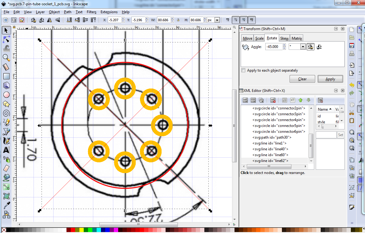
I should have seen this one coming , same problem as the 9 pin drawing. Same solution. I imported the jpeg to Inkscape then scaled the image til the current footprint and the jpeg pins overlap which sets the scale, then put in the construction lines again (in red instead of black this time) and that should give me the correct position of the pads, they need to move out to be centered on the red circle. Should be up in a few minutes.
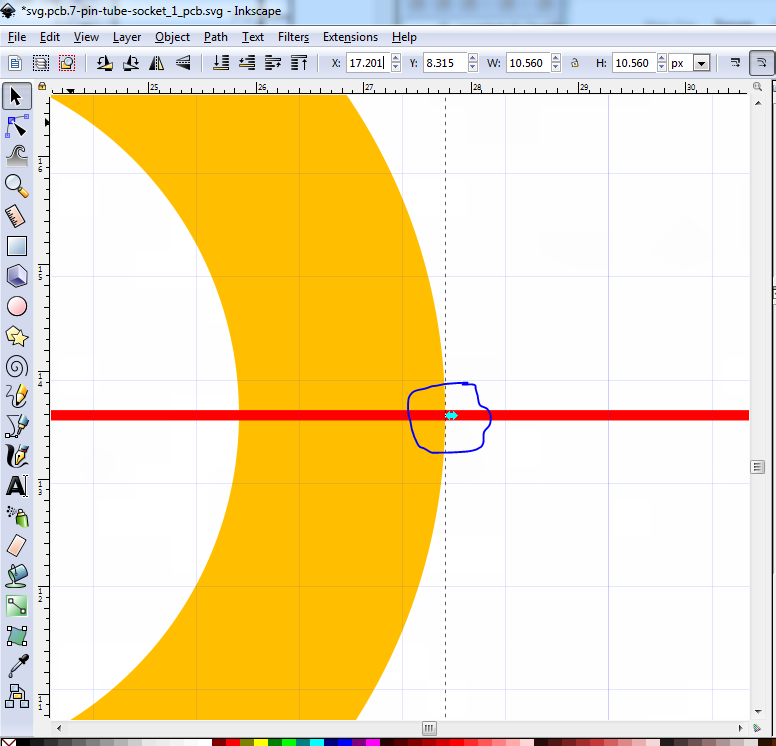
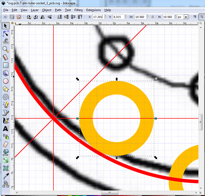
with the construction lines in place, I moved the pads via the inkscape tool bar (with the pad selected) until the arrows at the center of the circle in x and y line up with the x and y construction lines. With the tool bar in px (max resolution) you can get very close. Aligned like this the center of the circle is centered on the red circle where it should be.
the same applies to positioning the pad in y (in this case) at a fairly high zoom the center mark of the circle is fairly easy to get in the center of the construction line.
After this I deleted the jpg image in the svg, resized regrouped and saved, then copied the svg to breadboard and schematic and rezipped the .fzpz file to give the part.
Hope it works!
Peter,
New part looks right. Won’t know for sure until somebody prints out .svg of new part and checks w/ GZC7-Y1 socket.
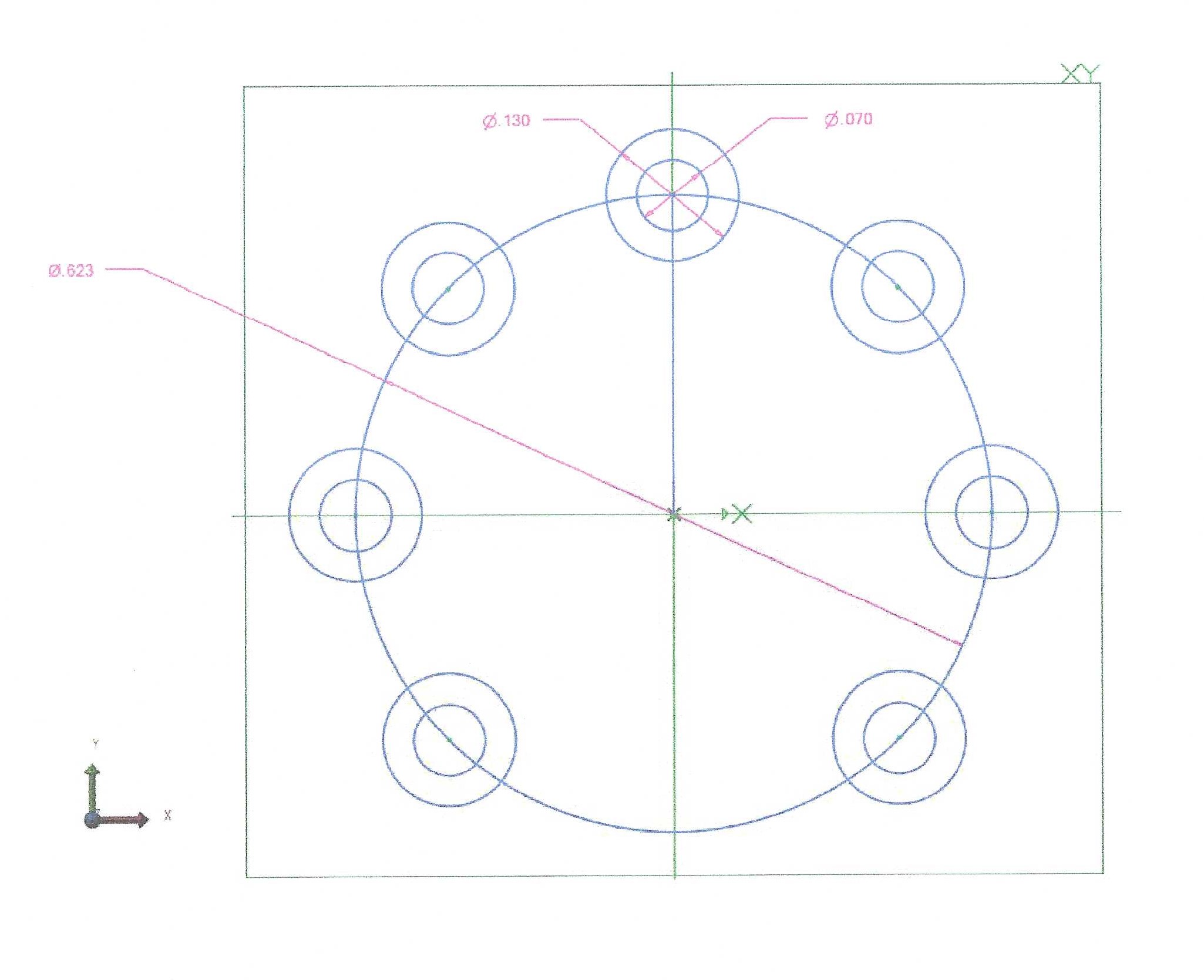
I really like the smaller OD silkscreen circle- is size from diagram of 18.6mm? if so, could you please change the OD of 9 pin socket to 25mm? this will help w/ parts placement around socket.
Thanks much!
Jim
It is actually 21.3mm diameter, the real 19mm diameter overlaps the pads and would be truncated, so increased the radius a bit to just clear the pads. I can do the same to the 9 pin easily.
Yes the real x y of each pad would make placement easy just set the x y coords in the tool bar for each pad, no construction lines. Here is an adjusted 9 pin socket, circle reduced from 30mm to 25 (in this case 25mm clears the pads):
Quick response here about Peter’s 7-pins socket. Downloaded and installed the .fzpz file in fritzing, printed it and discovered that the model is oversized when comparing it with the hardware version. If reducing it to around 75% then it seems to be fitting the hardware.
But I may be doing things wrong. When importing the socket into a fritzing pcb design,
I do not know how to reduce it so I cannot do that corrections myself.
The circle diameter crossing the heart of the pin holes should be 9.5 mm, but it exceeds this 9.5 mm
But again, I my be doing things wrong.
Is that the diameter of the socket pins? @oemcar though that is the diameter of the pins on the tube (as it is on the 9 pin version) so I changed it to be what looked to be the diameter of the pins on the socket from the jpg (which is of course not necessarily close to reality .) Could you measure the outside diameter of the circle of the socket pins with calipers? That is the measurement I need to get the pins in the correct place.


 I need to find a way to get the angles for the pins, but I think with lines and rotate in Inkscape it should be doable. I’ll give it a shot.