Measuring the pin outline of the hardware socket I measure about 15 mm. So the diameter of the circle where the pins have to fit into the holes is 15 mm. The holes are 1.7 mm diameter because the pins are having that outline. 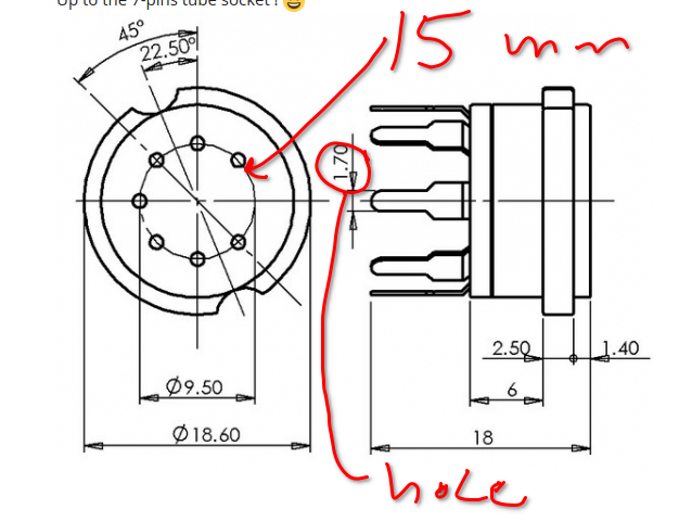
That is what I did originally. That should be what tube-socket-7pin.fzpz a couple of posts above is. Then I changed up to tube-socket-7pin-1.fzpz based on this theory (your drawing with more lines  ):
):
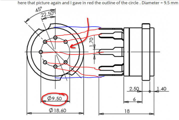
What happened on the 9pin socket is that the 9.5 diameter is of the pins of the tube that plugs in. The socket (as we see from the blue and red lines going to the picture of the socket on the right) are on a bit further out, the diameter corresponding to the 2nd circle from the outside. If the 9.5mm is correct then tube-socket-7pin.fzpz should be correct. Luckily I kept the original instead of replacing it!
Peter
Peter, you are absolutely correct. I should have realized that the left part of the drawing is the topview of the socket and for pcb purpose the right part pin outline with those pins
pointing to the left, that larger circle (with your blue lines in the drawing) is important for the holes in the pcb. This larger circuit, when measured with my caliper gauge, is 15 mm when I take the hardware socket.
Sorry for my mistake, it is me who is to blame putting you on the wrong track ! 
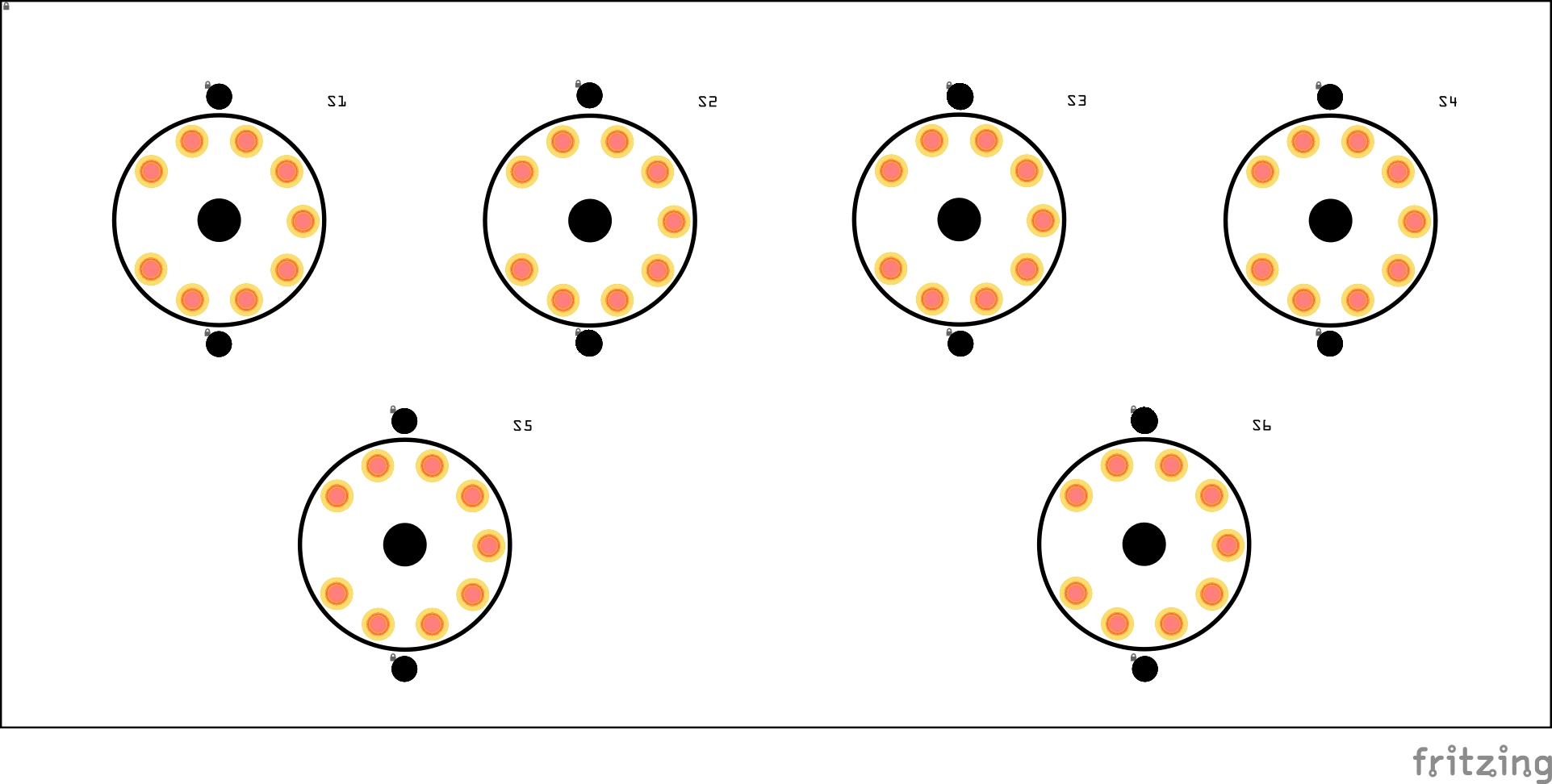
The circle diameter I used is 16.789mm so slightly larger that the 15mm measured for the pins. So it would be worth while to check with a 0.07in hole to see if a pin will fit or it needs to be a bit bigger to allow for more slop on the pins. I see the hole size should actually be 0.071in to match a #94 drill (although I think the board houses use .5mm increments for drills). What would be ideal is to print out the footprint and drill the holes with a #94 drill in a piece of plastic and make sure the socket fits mechanically (or cut some boards, but the plastic is probably cheaper and faster .)
Peter