Trying to make a 52 pin ecu connector part

Hey Everyone,

I am trying to design a PNP break out board for the 52 pin ecu connector. Fritzing doesnt have that connector so i am trying to import it into the software. I have the CAD drawing and dimensions from www.te.com for the connector, What application you use, trying to work my way around InkScape but just to size the circle pins is a pain

Hi there, and welcome aboard!

Part creation can be a bit of a challenge. In order to best help you, please post up as much relevant information as you can. I’m not exactly sure what type of connector/part you are trying to make, but I assume it’s an automotive connector.

In inkscape, if you are creating a breadboard view male pin, use the circle tool and turn off the stroke to the circle you create. To size the circle, use the ‘w’ & ‘h’ boxes at the top, above the workspace. If I want a 0.36 inch pin I would use the circle tool to create just a circle. Make sure the circle’ fill is set to the color I want, and turn off the stroke. Then I would enter my dimensions in the ‘w’ & ‘h’ boxes to accurately size the circle that will be my pin.

Anyway, post up some info, and I’m sure you will get some help.
Randy

1 Like

Yes it is an automotive connector, part number 172319-1.
https://www.te.com/usa-en/product-172319-1.html

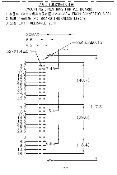
The dimensions and drawings for that connector is listed in the website above, the file is a pdf and its not allowed to post here, so I took snippets of that file.

I want to make all three views but the PCB view for especially for this connector.

That is going to be a bit of work to create in Inkscape. The dimensions are all based off of the top mounting hole. For example, the top most row of connectors are 7.45 mm down from the mounting hole. The right connector hole is 6.6 mm left of the mounting hole, and the other connector hole is 4.6 mm left of the other hole. All thoe measurements are from the center of the holes.

Here is where things are going to get tricky, Inkscape’s dimensions start at the bottom left of the page, or the object. If you want to precisely place a circle in Inkscape, you can’t use the center point of the circle as the location of the circle. Instead, you have to use the bottom left location of a square that is the same size as the circle. For example, when you select a circle that has already been created in Inkscape, it will be highlighted with a square box. It’s the bottom left corner of that box that is the location value in Inkscape.

I did whip up a PCB silkscreen outline of the connector in Inkscape. Once you figure out where the first few holes should be placed (mounting holes, and the top row of connector holes) adding the rest of the connector holes will be easy…

If you could get an svg image of the mounting holes you posted from CAD software, or create an svg image in CAD software, it might be faster and produce a starting point for editing with Inkscape to add details like copper ring around the holes.

Randy

auto_connector|36x125

You can not post a pdf directly here, but you can post a link to a pdf. I also grabbed the dxf from the site, which got a few more details for dimensions.

Using raw svg is easier (and more accurate) for something simple like this. The coordinates start from top left, and circles are placed by center coordinate and radius. I just calculated coordinates numerically from the dimensions. I don’t know what the pin numbering sequence should really be. I started at the outer top pin, went down, then up the inner pins. I only drew the mounting holes on the silkscreen, without making them holes to be drilled. When placed on the pcb view, a hole part can be overlaid to create an actual hole.

svg.pcb.172319-1_pcb

I have the wiring diagram for the ECU so the number I will add the number sequence. I know this in the advance section however I’m new to both, Fritzing and InkScape software. Thanks for the drawing of the connector from @just_randy and yourself It helps a lot. I really would like to know how to create it so that I can make other components as needs be (is there any proper how to create a part in Fritzing, I’m seeing videos but they are all over the place).

Thanks again guys, appreciate it.

There is also a “Parts Help” category here, which is probably where this belongs. It is not necessary to use Inkscape. Any tool that can create valid svg files will work fine. Inkscape is referenced a lot because it is free and commonly available.

The official documentation for the graphics is out of date in a lot of places. I would not recommend using the template files linked at the bottom. I use units of in (inches) or mm (millimeters) for breadboard and pcb, depending on the units in the source information. Schematic is always in inches, to make matching to the 0.1in grid easy. With the document in inches, I use 1000 px per inch (px = mil). For mm, I use 100 px per mm. That makes it easy to convert from px to units and back when positioning and scaling the graphics.

The most recent tutorial information I know of is in the “Tutorials - Guides - How to’s & Experiences” category here on the forum, starting at Part creation howto part 1 - breadboard and pcb. Another fairly official reference is 2.1 part file format from the wiki. I did some updates on that a month ago, so it is better than some information. It is more background and reference information, not a how to guide.

While working with this, you need to stay aware that there are 2 difference contexts for parts and parts creation. There are core parts, the originals of which are stored in the parts library on github, and there are individual and groups of parts that can be imported into local ‘bins’. Both use the same files, but there are a few differences in names and storage locations, as well as subtle differences in the definition content. The Parts editor can be used to create individual parts. As long as the rules are followed, it is not necessary to use the supplied parts editor. It has bugs and limitations. My background lets me read and edit the xml files (both the fzp definition and svg images) directly (with a text editor).

There is a FritzingCheckPart tool available to help look for some common errors, and do some cleanup of the files [to be] used for a part. It is recent, and out of date too. Some of the rules that it applies may not be what is really desired. It does catch a lot of simple errors though. A new version is being developed (slowly).

A part (fzpz) file is just a zip file containing a single definition (fzp) file and up to 4 image (svg) files. How each of those gets created does not matter. Inkscape, Illustrator, and others for the image files, Part editor, or xml editor for the fzp. zip or Parts Editor for the fzpz file. Fritzing has limitations on the svg images that it can process, so the tools used need to be able to create an svg file that follows the rules for TinySVG.
1 Like

So this is what you meant when you said

???

I assumed that was what you meant, but I still googled around looking at maybe somehow Inkscape could work using center points instead of the lower left corner stuff it does.

Inkscape can be extended using python scripts (like any modern software package can) that would make it more fritzing friendly, if someone was inclined to do so…

@sawboss didn’t mean to hijack your thread… Forum users here are pretty helpful, and will point you in the direction you need to go. I am a bit of a car guy, also a bit of hacker, so I am curious as to what you are doing with an ECU connector.???

Randy

Yep. svg is xml, which is just structured text. A basic circle looks like

        <circle
          cx="460"
          cy="370"
          id="connector50pin"
          r="95.4"
        />

with center at “cx”, “cy” and radius of “r”. Coordinates relative to the block (group) it is contained in. In this case, it also inherits the stroke size and width from a wrapping group too.

  <g
    id="copper1"
    fill="none"
    stroke="#f7bd13"
    stroke-width="50"
    transform="translate(120.8,360)"
  >

This is fussy about some details, but is not complicated.

I too am a car guy, with IT skills (software programming to be exact), just new to Fritzing, InkScape, or vector tools, I am a total newbie with less than a week experience. I love the answers from the members for far, I really appreciate it especially the way @microMerlin has shown that it can be done from XML. However, to answer your question, I’m making a Plug and Playboard for the 52 pin connector to use with Speeduino v0.4 board, as well as Megasquirt and others.

I always have done wiring and assembly of cars using Megasuirt, but I always wanted to know what tools to create these boards and I just stumbled on this awesome tool, and just being a sponge right now. Thanks, everyone for your help this far, I’m excited maybe too much.

This is exactly what the doctor ordered… perfect

Ah! Another with IT and software development background.

If you are going that direction, here is an svg reference I use. Not everything thing there applies to TinySVG, but the info is accurate when it does apply, and easy to lookup. You will not want to place any element with a stroke width at the exact edge (IE 0,0) of a drawing. The stroke extends both directions from the element edge by half the width. So to keep the stroke actually in the drawing, offset by half the stroke width. Filled elements with no stroke can move right to the edge. You will see that in the pcb svg I uploaded earlier. I also left comments in there about how the coordinates were calculated, though the source numbers are not labeled.

The main elements I use are line, rect, circle, g, path, text, desc. Get comfortable with the attributes for the svg element. That is where units are set (height and width), as well as the translation of that to px (the viewBox attribute).

Just unzip one of these and you will see how it’s made.