Here’s a part for the Teensy 4.1, based on the Teensy 3.6 from Nic Newdigate.
As a novice fritzing user, there’s likely things that can be improved. I’m happy to make changes as needed. Hopefully this can be useful to someone else.
although there appear to be more connectors on the 4.1 part.
The svgs are missing layerIds (which will casue the part to not export as an image.) To correct this do edit select all then group and name the group breadboard or schematic depending on the svg involved.
Schematic lacks terminalId which causes the connection to the middle of the pin rather than the end.
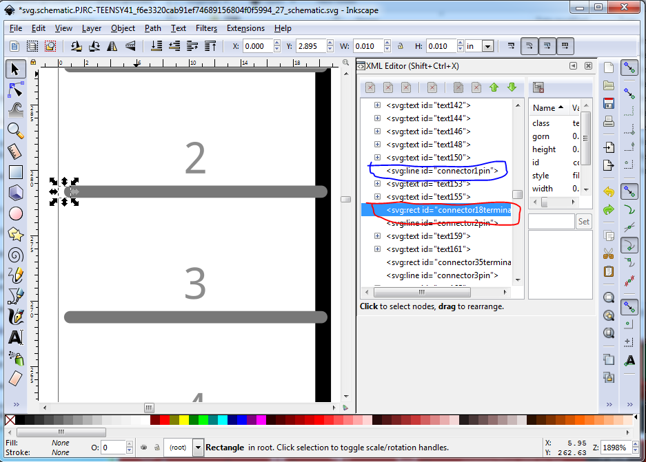
The terminalIds appear to be present but not properly configured. Here is an example for connector1 (connector0’s terminalId appears to be missing, just duplicate the connector1terminal rectangle and move it up .1in and rename it to connector0terminal):
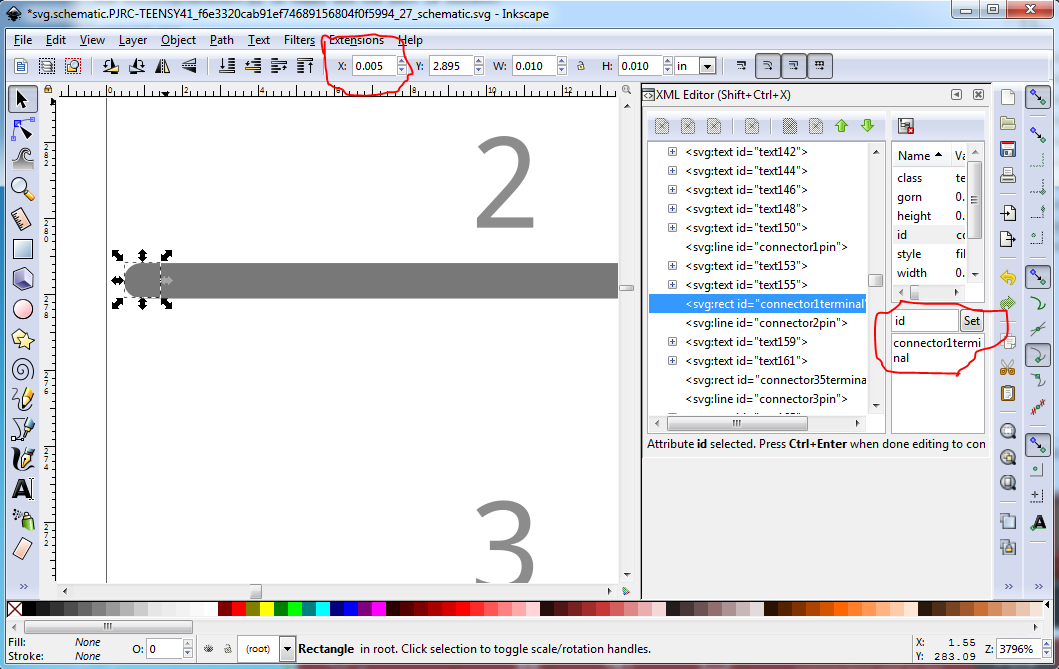
This corrects both problems. The x coord was changed from 0 to 0.005in and the id from connector18terminal to connector1terminal to create the correct alignment. The same needs to be done for all the other pins.
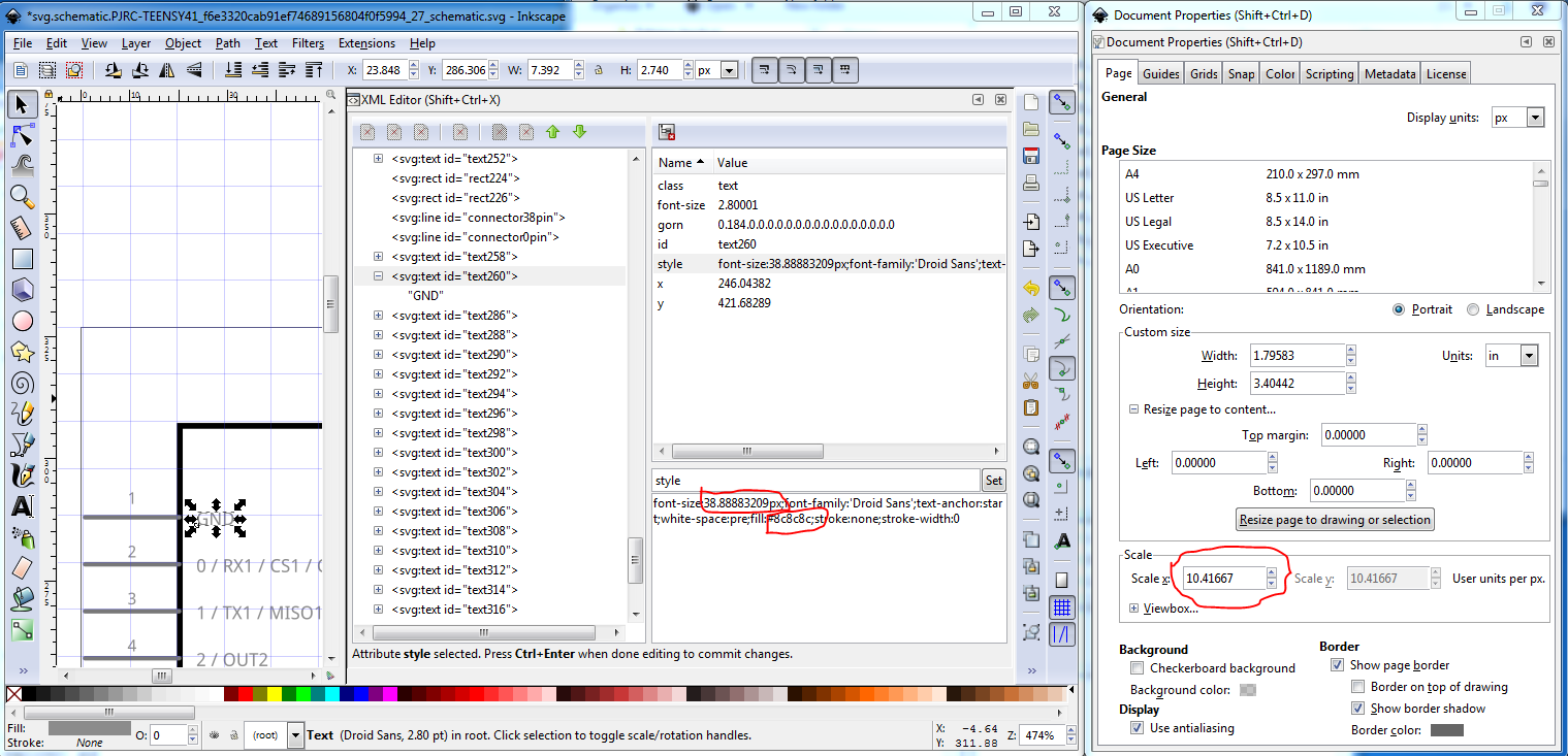
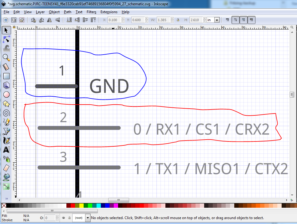
Both the font size (around 38px rather than 49px) and fill color (#8c8c8c) need to change to 49px and #555555 to match the graphic standard and to improve readability. It is desirable that the pin lengths change to .1in from .2in (which saves space in schematic which is always short!) as well.
before (but after rescaling the svg which is detailed here):
note this may not work correctly in Inkscape 1.0 (it didn’t in the beta!) I still use 0.94
Here pin 1 has the correct (darker) #555555 fill a font-size of 35px for the pin number and 49px for the label making the label larger and more readable (as well as meeting the graphics standard.) The pin has been reduced to be 0.1in long rather than .2in.
pcb lacks the silkscreen layerId which is why the board outline is not showing up in pcb view.
Error 53: File
‘part.PJRC-TEENSY41_f6e3320cab91ef74689156804f0f5994_1.fzp.bak’
At line 785
Bus nodeMember connector15 doesn’t exist
indicates that connector15 (likely one of the interior pads) got deleted but its associated bus definition did not. As well I expect the gnd2 pin should be in the ground bus but is not.
This tutorial series may give you information on how to correct the issues:
Thanks so much for the detailed response. That clears up some confusion I had with some of the output of FritzingCheckPart. I’m incorporating your suggestions and should have a new version (and maybe some questions) in a couple days.
Note this part has one error (that I can’t fix): the ethernet connector is 2mm not 0.1in and is thus in the wrong place and the wrong size in pcb (and in breadboard.) In practice you are unlikely to want to use the ethernet ( a ribbon cable which will work is the more sensible choice) but be aware the part is wrong in that area. To fix this I would need to know the position of the 2mm ethernet connector. I didn’t change the moduleId so you will need to delete the current part before being able to load this one.
Thank you for creating and sharing the Teensy 4.1.
I am trying to use the schematic view but the pin doesn’t seem to match the actual
See below for example TX1 should be pin1 but it shows as pin 14 etc…
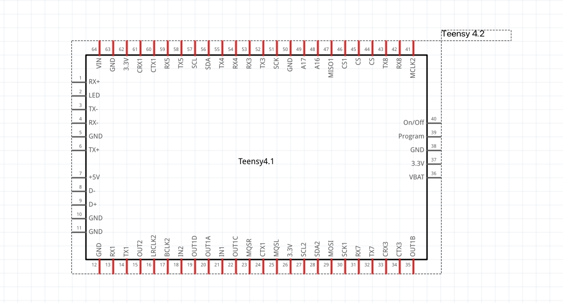
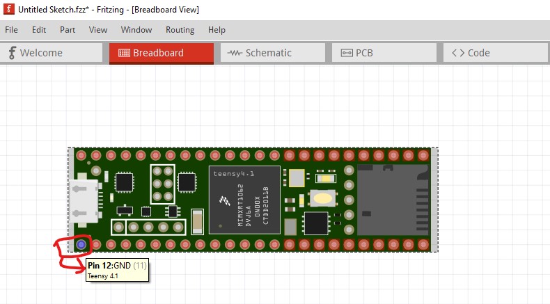
The issue is in the original part (I just changed some of the broken things in the part that was posted.) The original part is not numbered in the standard Fritzing manner:
in this part pin 1 is on this internal connector. In a standard Fritzing part pin 1 would be the bottom left pin (as with an IC) like this (which in this part is pin 12.)
This doesn’t affect anything except the pin numbers, the part will still work fine it just likely doesn’t match the pin numbers in the documentation. If I noticed this (which I may not have) when I modified the part I decided not to change the existing numbering (which is a fair amount of work!) It is possible (but as noted a fair amount of work) to correct the pin numbers in a new part, but I have not done so.
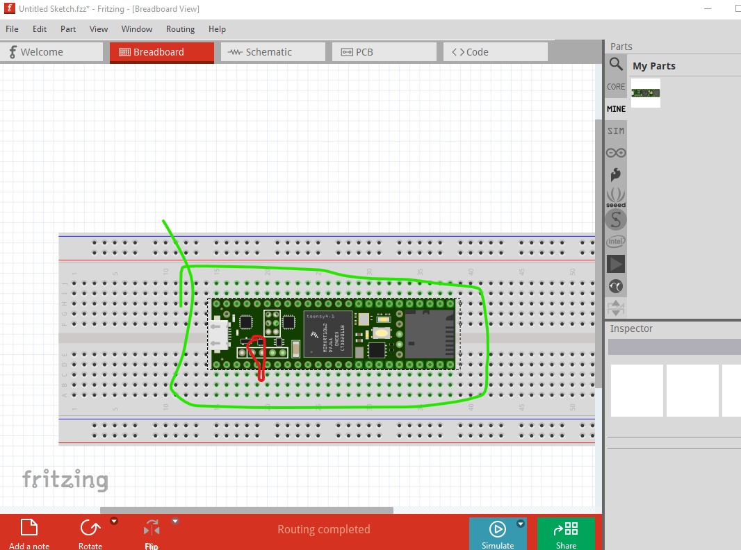
If I drag this part (the fixed version) onto the default breadboard in a brand new project, the grid doesn’t allow me to align its pins with the breadboard holes. I can work around this by temporarily turning off the grid, but it’s a bit annoying.
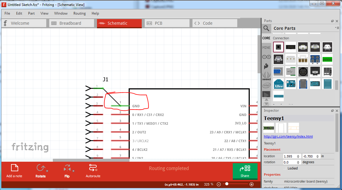
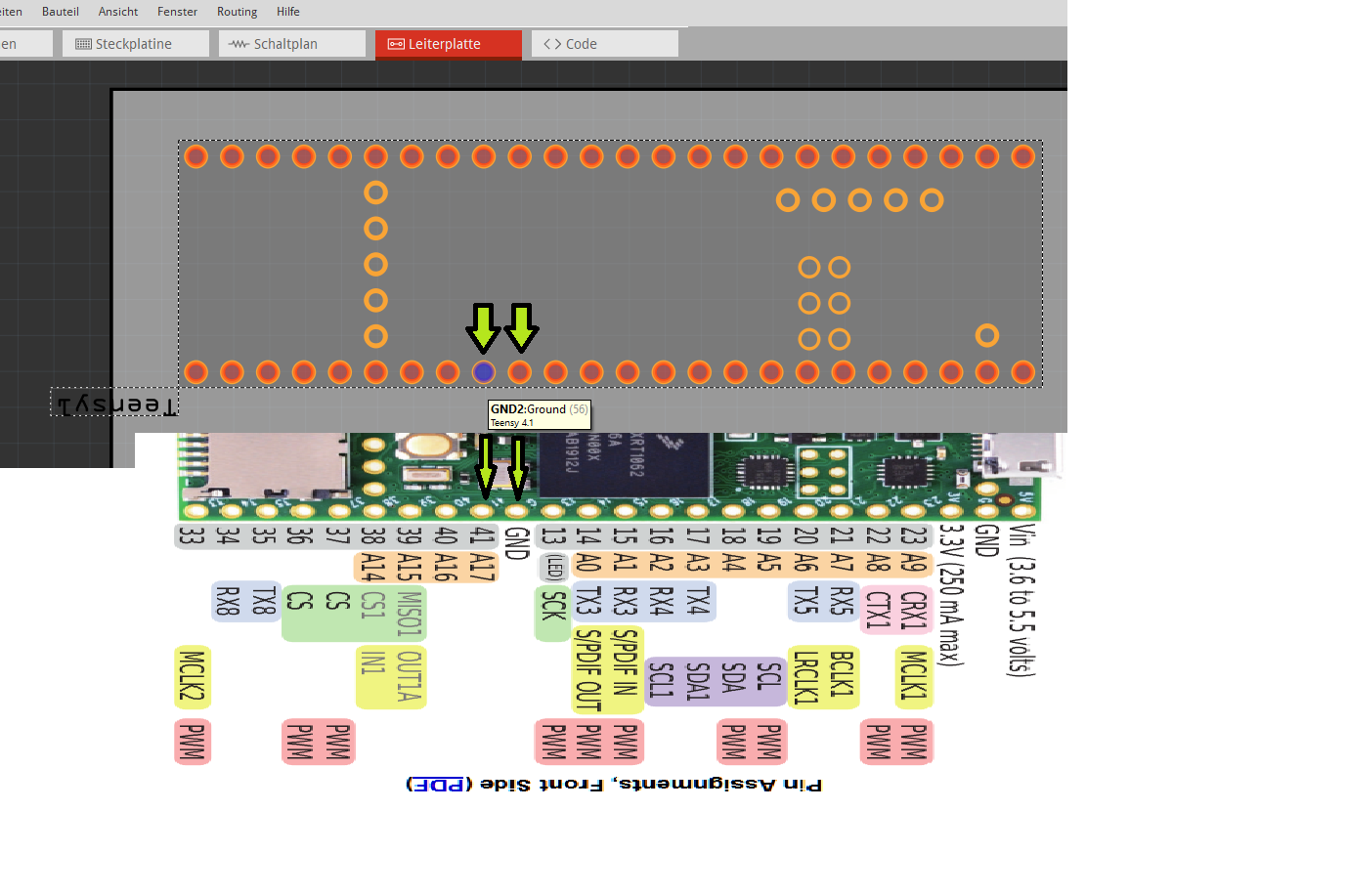
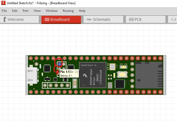
Yep. Known Fritzing quirk. What is happening is the middle pins (circled in red here, and set to type female so it will not connect to breadboard and thus short with the main pins on the breadboard, but they can be selected to align to the grid apparently at random on part load!)
are offset 0.05in in X. In this case the main pins got aligned to the grid and the part connects to breadboard correctly (all the main pins are green.) If Fritzing decided to align to one of the pins that is 0.05in off in X they would not connect to breadboard as they are 0.05in misaligned. Fritzing appears to decide at random which pin should align to the grid so sometimes the alignment is wrong. Setting the grid size to 0.05in in View will cure this (you may need to move the part one 0.05in grid position to get it to align correctly though.) This is a known issue but hasn’t yet been fixed. It has been requested to be able to select which pin is used for alignment to the grid (or to at least always use the same pin) but that has not yet been implemented (and then the parts would need to be modified as well to spicify which pin to align to which may be why it hasn’t been done as that is a lot of work!)
 I’ll post a new version when those are addressed.