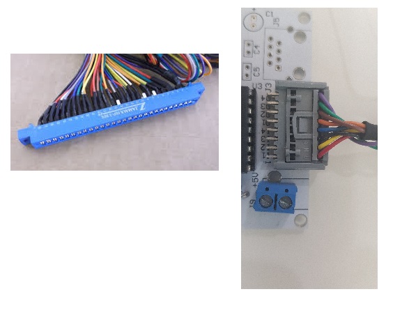
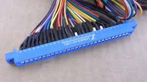
Hello everyone. I need the STOCKO connector model designed in Fritzing so that I can import that model and use on bread board. Check the attached image. I need models of these two connectors on Fritzing.
I need following connectors
1- Stocko Connector 8 pins
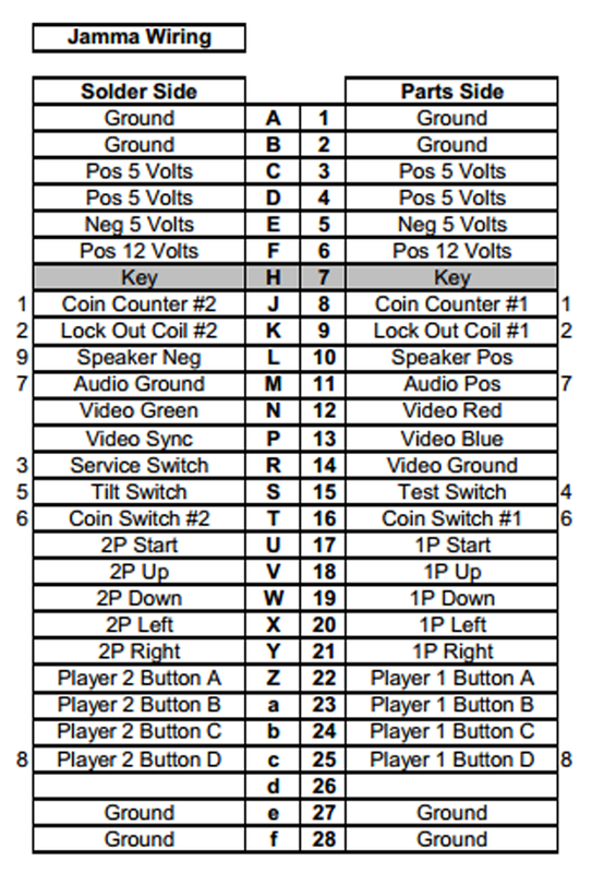
2- Jamma Connector 28 x 2 pins
Please let me know if anyone can design these connectors.
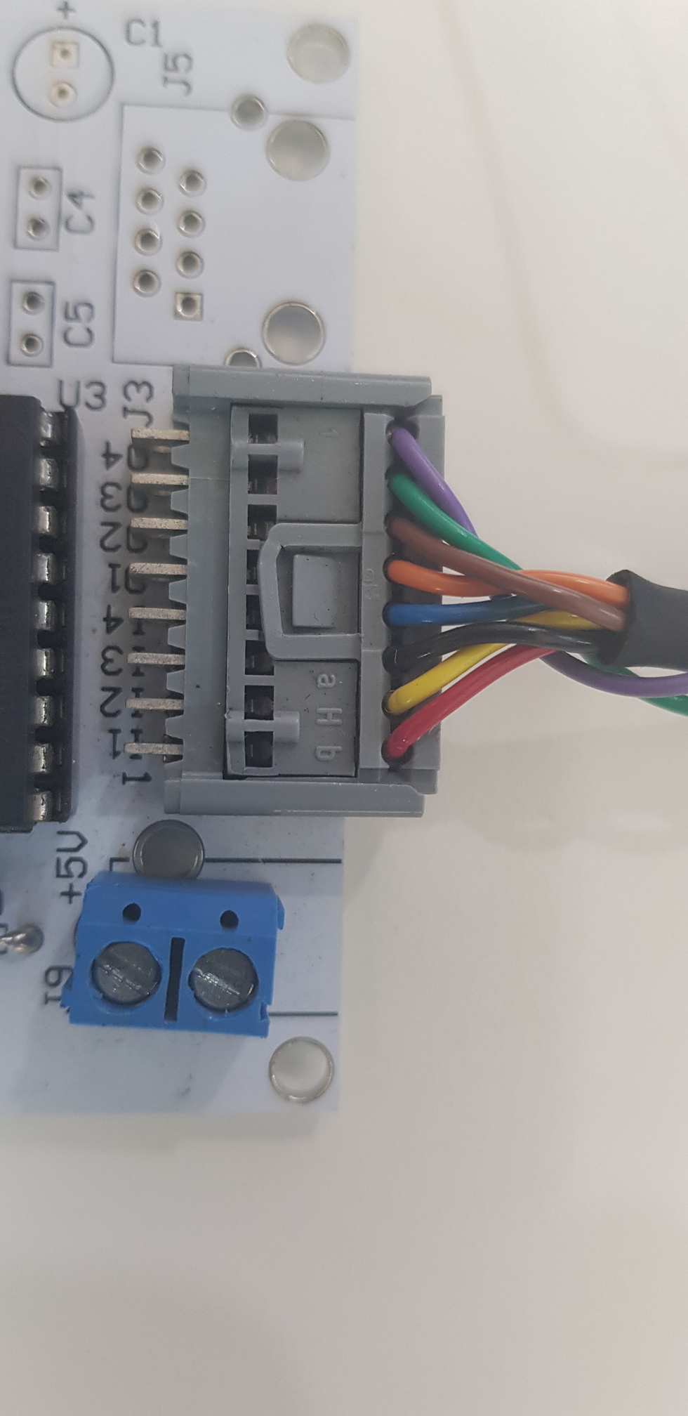
From the image, the Stocko connector looks like it is (ends with) a standard 90° single row header, so the header part in Fritzing should be functionally the same. With the limitation that no parts can be placed on one side of it on pcb.
So the connector itself does not have any pins at all? One side connects directly to wires, the other to a header? If that is the case, the connector would not go on the pcb at all. Just the footprint for the header (which is a different part). That “connector” is just 8 wire segments from one side to the other. Other than the “picture” in breadboard view, what would this actually DO in Fritzing?
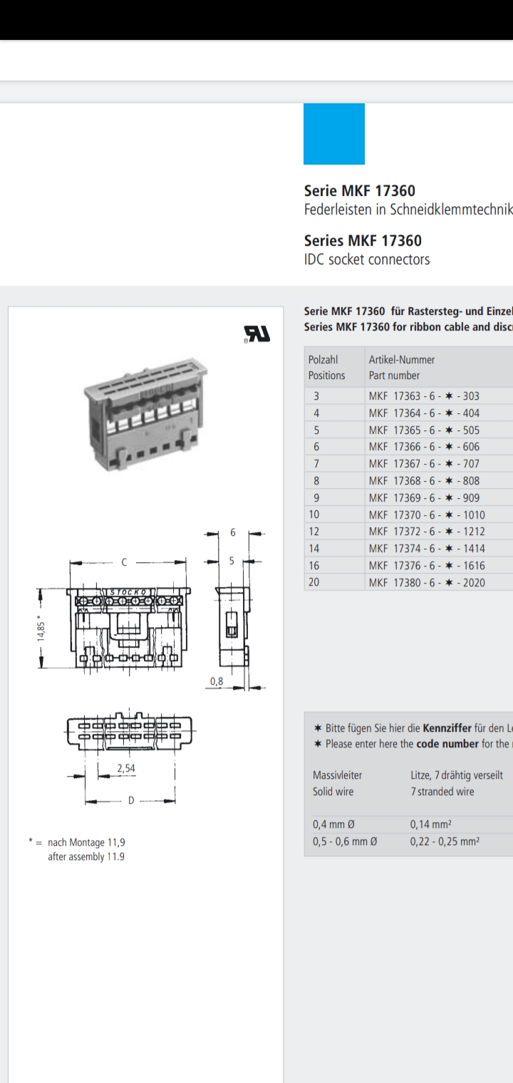
A link to (a source for) the full data sheet would be better than a screen shot from a single page.
It’s pretty vague, but the MKF13470 looks like a ribbon cable to edge connector.
What is this MKF17368?
We are volunteers giving free time and we need people requesting stuff to link detailed engineering drawings and pics, so we kinda need more info. I can even see in the pic if the connector is PCB mounted or edge connect. If it is edge connect that’s a problem in FZ, so you will have to search the forum for that.
Ah, edge connector! A detail that was not at all visible in the screen shot, but the linked page explicitly shows “Series MKF 13470 IDC edge connectors”.
I believe that is possible in Fritzing, but (most or all) of the tutorials and guides assume either a through hole part, or smd part. An edge connector is effectively smd on both sides of the board. The svg for the pcb needs to have the copper0 and copper1 layers setup differently, and my current information is that the parts editor does not handle that. The part needs to be created by manually editing the xml instead of using the Parts Editor tool.
If someone wants to provide the basic svg view images, (I am pretty sure) I can adjust the pcb image, create the xml and part file.
The link is to a MKF 13470 IDC edge connector, but the pic above shows the presumed MKF17368 sitting on a white PCB, so who knows what’s going on. I’ve already wasted 20min trying to find info, and can’t make it due to RSI, but if there was correct info maybe someone will look at it.
Vanepp did the work on edge connectors, and I think he said if you make one part with pads above and below, they connect in FZ. Maybe he made 2 separate parts so someone will have to look up the post.
Hello Old Grey, please reply. I need this part made asap. please leave me your email address and I will send you datasheet of the connector.
Btw, I checked your post of video tutorials on creating Fritzing parts, but tbh I am very short of time and I need this connector made on urgent basis.
Rename the .pdf to .fzpz, then upload that with a note about what was done (so others know to rename again before use). A link to a web resource is better.
Blasting multiple repeat messages for the same thing, in multiple threads is NOT a way get volunteers interested in helping.
When I said “basic svg view images”, i meant just that. Svg files that are usable (or very close) as the images for each view needed for the Fritzing part. Not jpg. Jpg is a bitmap format. SVG is vector. Totally different thing.
@microMerlin I am unable to convert .pdf to .fzpz. Also I do not have more pictures other than I have uploaded. Whatever I had I uploaded. I either do not have the svg equivalent of these pics. I am basically looking for someone who can do it from scratch, and finally give me the models sch, pcb and bread board that I can import in fritzing. If you can help me, reply, otherwise do not bother. Don’t
get hot like sitting on the stove. Let others give chance and reply .
I did not say “convert”. I said “rename”. Since you posted a link, that is not needed anyway.
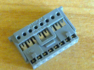
That MKF17368 connector is electrically trivial. It just straight through connects 8 wires at one end to 8 pairs of slots at the other end. It does not need a pcb foot print at all. It would connect (I expect) to a header on the pcb, but that is a different part. Since internally, it is just wires, the schematic view can be one of the standard headers. Breadboard view is (electrically) 3 Fritzing connectors per position, all wired together (a bus). All that is needed is an SVG image, probably in close to end on perspective view, of the connector. The view chosen to allow access to all of the connection points, but now use up too much space. Alternatively, a flatter (side) view would work, making the image more recognizable, but using more space, and fudging the positions of the slots under the part.
Here is what should be a functional Fritzing mkf17368 part. The breadboard graphics are ‘raw’, but the part should be usable. If someone wants to provide a better breadboard view svg image, I can merge it in.
As said before, pictures are not usually enough to create a proper part file. Dimension information is needed too. Which (probably) comes from a data sheet. This one IS going to need a proper PCB footprint.