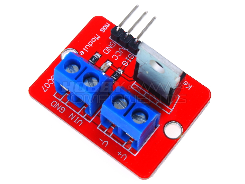
Does anyone have a Fritzing version of this part or know where I can find it?:
http://hobbycomponents.com/images/forum/HCMODU0083_800_600.JPG
Thanks
-Wes
Does anyone have a Fritzing version of this part or know where I can find it?:
http://hobbycomponents.com/images/forum/HCMODU0083_800_600.JPG
Thanks
-Wes
Don’t see one anywhere. To make one we would need a mechanical drawing with the location of the holes and connectors which I also don’t see in a quick search.
Peter
Found one diagram:
It is enough for the making of the fritzing part.
Can I ask you, how soon you need it? And what are you trying to design with it? 
I am very new to fritzing so I was hoping to find the part already defined somewhere.
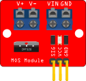
Here’s a drawing I made of the part:
Here’s the schematic:
IFR520_MOSFET_Module_Schematic.png
Hopefully that will help if someone is willing to create the part.
-Wes
I’m not in a hurry for the part. I was hoping to use fritzing to document a project that I’ve already built so I can share it with others. The project is a power management system for the Raspberry Pi when it is used in an automobile. It insures that the Raspberry Pi shuts down gracefully when the car’s ignition is switched OFF.
I think this module is the only part that I’m using that isn’t already in the fritzing libray.
-Wes
That drawing is very helpful along with my diagram since I can use it as base layout and place the correct component on illustrator. I will try it right now.
Quick question @vanepp: When creating the new part, I shall use the same size (on inches of course) when making this part?
Yes as noted in the other post you want to set the size in inches (which you have been doing). I have been working on a part between fighting with github on source changes today and am mostly finished. Here is rough outline of how I did it.
The fc51.fzpz file referred to is a similar board (but with only 3 pins where this one needs 7) that I made some months ago for someone. If you search for it in the forums it should come up. I’ll post a copy of it when I finish it in a bit.
edit the fc51.fzpz file in parts editor to change the metadata
export it as hcmmodu0083.fzpz
unzip it with 7zip to get the svg files
edit the breadboard svg with Inkscape
use deepungroup to ungroup everything
delete all components except the connector
resize the base rectangle to the dimensions of the new board change the color to red
from fritzing create a new part and export screw terminal 2 pin.
unzip the fzpz file with 7zip
edit in Inkscape the breadboard svg
ungroup everything. Copy the entire part via edit->copy
and copy it in to the new breadboard svg.
duplicate it for the 2n terminal
set a rectange on each of the four screw terminals as
connector3pin
connector4pin
connector5pin
connector6pin
need to add these to the fzp file as well)
copy in a to220 transitor case for the mosfet.
Align the pins to .1 boundaries
regroup it and set the id to breadboard.
schematic
ungroup everything
Set the connector terminal widths to 10thou (missed this when I made this part) on connectors 0-2. Made the rectangle larger and added pin / terminal and labels for connectors 3-6
(the screw terminals). Changed the text on the labels and pin numbers to reflect the new part.
PCB left as is, it only shows the 3 signal lines not the screw terminals (which causes some changes in the fzp file below).
fzp file:
left the pin 0 to 2 definitions as is.
Duplicated the connector2 entry (from connector to \connector) for pins 3 to 6. With the following changes:
in the breadboard defiintion
p svgId=“connector2pin” terminalId=“connector2terminal” layer=“breadboard”
changes to
p svgId=“connector2pin” layer=“breadboard”
because the screw terminals don’t have or need a terminal definition in the svg.
and the pcb view definition changes from
pcbview
p svgId=“connector2pin” layer="copper0
p svgId=“connector2pin” layer="copper1
\pcbview
to
pcbview
\pcbview
so the 4 screw terminals have no connectors in pcb view. Once it is all done run the part through FritzingCheckPart.py to check it, then copy the breadboard svg to the icon svg to set the correct icon and rezip the files in to an fzpz file suitable for loading to Fritzing. That gives us this part:
hcmmodu0083.fzpz (16.6 KB)
which the original poster can use for his project. What I would suggest for you is that you start from the fc51.fzpz file and see if you can get the same part I did (yours will have a new moduleId and thus load alongside the one above) follwoing the steps above using either Illustrator or Inkscape or both and ask about anything that isn’t clear.
Peter
Okay, I am here waiting for it. It is a good time to try Inkscape for the first time ![]()
I don’t know anything about Illustrator, or if you can muddle through INK knowing Illustrator - usually not -, but I made a INK/FZ part making vid series that teaches you both at once via my hacky GUI method.
Thank you so much for providing this fritzing part! Looking at your instructions, it seems it would have taken me forever to accomplish what you did in a day.
I’ve incorporated the new part into a fritzing breadboard layout that I will be posting on my personal website along with the Arduino code and other bits and pieces that are needed to make this power management system work.
Here’s a peek at the fritzing breadboard layout:
-Wes
You are most welcome. With experience making fritzing parts is fairly easy, getting the experience is less so, so for folks who want a fairly simple part it is often better for one of us that knows how to do it. In this case its a double win because @KingDarBoja wants to learn to make parts so you get your part and he gets an example of making a part to practice with (a triple win, because I got to make a part that worked relatively easily between the frustration of fighting with github to get some development code to stage properly which still isn’t done ).
Peter
Will this new part become part of the standard fritzing library so that others can find and use it?
-Wes
Probably eventually. To get it there I need to submit it via a pull request on github as that seems to be the only way parts are getting added at the moment. I have a list of a bunch that I need to do (all of them posted in the forum so they are available), but at the moment I am focused on trying to fix some of the bugs in the source. Posting here serves, as we will usually tell someone looking to do a google search which will find the part here (or I will remember making it and point them to it). If we can find some folks interested in helping and knowing parts creation there is a bunch of work to be done in cleaning up the parts in core, bit again that’s down my list a bit (the bugs that most annoy me are first ).
Peter
The extension doesn’t work due to the lack of xlml python module. Tried to install it but failed (due to Windows OS).
Its been a while, but it was either already in Inkscape or I just downloaded and installed the extension and it worked fine on my Win7 machine. Inkscape is written in Python I believe so python should be there. Note that deepungroup doesn’t always work (it will sometimes error out on a python error) and more importantly doesn’t undo translates while ungrouping which the Inkscape ungroup with shift-cntrl-g does, so I usually manually ungroup as I want to eliminate most translates (polygon translates apparently can’t be removed except by doing it manually by moving the points).
Peter
So far, the result (as .PNG). Took me a while to understand how layers and such things work on Inkscape.
EDIT: Here is the .svg file IFR520_breadboard.fzbz (6.6 KB)
You can upload svg, at least that way we can see if something looks strange.
Did FZ accept it.
Looks good, a few issues:
In Inkscape
ungroup everything to remove the transforms.
edit->select all
file->Document properties->resize page to content->Resize page to drawing or selection
to resize the origin to 0 (you should do this before regrouping on all svgs for fritzing)
note in the scale section of document properties that the scale is 0.01042 not 10.41667 which it should be to get the viewbox from the current viewbox 0 0 1.319322 1.0042583 to thte correct 0 0 1310.9322 1004.2583 which we are going to correct here.
with the entire drawing selected record the current size in px
x 0 y 0 w 125.712 h 117.648
edit->preferences->Behaviour->transoforms and make sure
scale stroke width is ticked (I normally untick this so Inkscape doesn’t change stroke widths on scaling but here it needs to be ticked for this to work).
now in doc properties change the scale to 10.4166 and click on the drawing. The image disappears (and unselects as well)
drag a selection rectangle around the top left corner and you get a selection (your image at the new scale)
edit-select all
the tool bar in px says
x 0.000 y 117.531 w 0.126 h 0.118
change that back to
x 0 y 0 w 125.712 h 117.648
and the drawing is now as it was except the viewbox is now
0 0 1309.4964 1225.4964
almost as it should be (I usually set the view box values to exactly match the height and width at this point).
in xml editor
select svg:text=“label” and change id from label to text3683 (chosen at random from another text string). label is special and Fritzing will replace it with the chip label from the fzp file which isn’t what is wanted here.
drag a select rectangle to enclose the three white connector dots on the IRF520 part and delete them. (this is optional, it won’t hurt anything to leave them there, but it reduces clutter when looking for connectors they are labeled as connectors in xml editor)
Change the tool bar units to in then click on each of connector0-6 and verify they pins are on .1 boundaries (which they are, good work!)
Set terminal IDs for the 3 .1 gold pins. At present with only a pin defined the conneciton will be to the center of the pin. While that is fine for the screw terminals of the headers we want the connetion to be at the bottom of the pin, not the middle. So duplicate a rectangle (I used “upperstripe” just below connector2pin)
That created rect994 at the bottom of xml edior
in the tool bar change height and width to .01in (10 thou)
in xml editor select the transform (scale 1,-1) and delete the (scale 1,-1) (replace it with blanks) and hit set
the transform is removed and the rectangle moves up in the drawing. Still in xml editor
change height and width to 10
change style to fill:none;stroke-width:0
this creates an invisible rectangle which will become our terminal so now change id to
connector0terminal and set it to make the change. We now have the terminal but it is in the wrong place, so go to the tool bar and set x to 0.8 (from .210) which moves it to the x position of connector0pin-1 (which is the incorrect name, so in xml editor change the id to connector0pin and set it). Set y to 0 which moves it to the approximate end of the terminal where we want it. Repeat this step (by duplicating connector0terminal and changing x by .1 higher to move it to the next pin and renaming it connector1terminal)
Now we have the 3 terminals we need to align them properly (note, if you can make it work which I usually can’t this is easier in parts editor).
I notice that the pins all have a transform (scale -1) since I dislike transforms (as in my view should you) I removed them by replacing them with blanks in xml editor
connector2pin x 0.807 y 0.010
remove transform
x -0.839 y 2.341
change back to
x 0.807 y 0.010 via the tool bar and the pin is in the right place without the transform.
and it is back in position without the transform.
repeat for 1 and 2
Now with the pins in the proper place and without transforms move the terminals in to postion
because the pin is .032 wide and the teminal is only .01 wide, the x coord is a little larger to center the terminal on the pin. In my case I used x 0.817 instead of the 0.807 for the pin and .01 for y. The next two pins are .1 larger in x, so repeat twice more to get the pins correctly positioned.
Almost done, one last thing: set the layerId to breadboard.
edit->select all
object group
change the id of the resulting group to breadboard
and we are done.
file>save as->plain svg
save replace then exit Inkscape without saving (it will want to replace the plain svg with Inkscape svg which we don’t want.)
Now rename
IFR520_breadboard.svg
to
IFR520_breadboard.fzpz
because the forum sometimes has problems uploading svg files. When you download this change the name back to .svg and you are away. Hopefully the formatting in this is ok …
So all that said here is my corrected svg file (named .fzpz):
IFR520_breadboard.fzpz (51.7 KB)
change it back to svg to display it. Note it will have px in the font-sizes as I didn’t post process it, and the terminalId defintions will need to be added either via parts editor (or if it is me via a text editor  ) to the fzp file for the part. I’ll probably be out for the rest of the day so response may be delayed.
Peter
Looks good, only 2 minor nits, there isn’t a layerId in the schematic svg, you need to do a select all, group and change the id to schematic to fix that. The only thing that breaks (as far as I know) is the part won’t export as an svg, this part will be missing.
The other thing is the pins on the screw terminals in breadboard are slightly off the .1 grid. It is preferable that they are on the grid, doesn’t affect function just looks a little messy. You have caught on to parts making quickly!
Peter
