Here is an improved version of the Raspberry PI GPIO header for shields. The improvements are:
Breadboard:
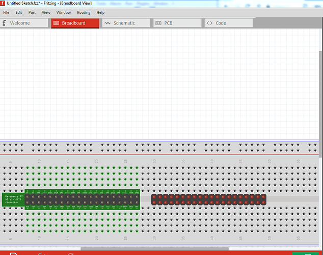
Put the connector on an adapter board with a .4in pitch so it will connect in the center of the breadboard like this, and add pin labels:
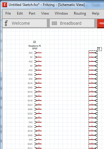
The new part is on the left and the original part on the right. You can not connect to the header pins directly in the new part, only via the connectors on the breadboard. Schematic has not changed a lot, only pin labels were added:
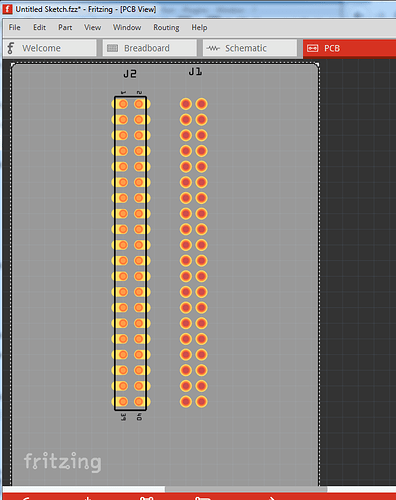
The direction of the connector was flipped (so input is on the right as is standard practice) and pin labels were added. The big change is in pcb. Because on a shield the GPIO connector is near the edge of the board the only routing choice is between the pins. With circular pads that is possible but not all that easy. So I changed the pads to be narrower oblong pads to allow easier routing between the pads:
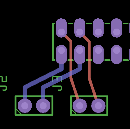
Example gerber output with 4 connectors with traces (note to do this you need to reduce the pcb grid size from the default 0.1in to 0.05in and reduce the trace size from the default 24 mil to 16mil in Inspector for any trace going between pins. With those two changes the part passes default settings DRC):

and finally the new part then its test sketch (which has all 40 pins connected out one side:
edit: this part is broken if used on the bottom of the board, so I deleted it and replaced it with a part below in this thread that works correctly. If you have downloaded this part, please replace it with the new one below!
It is my intent to change the code of the part factory to have an option to generate this type of PCB footprint for both headers and ICs (as the function is useful for both) but I don’t have a time frame for completion (other than likely long  )
)
Peter


