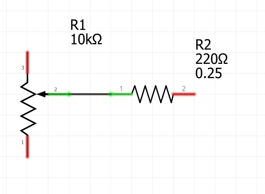
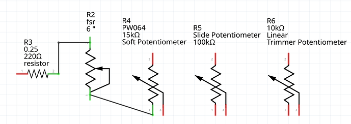
Potentiometer symbol

Hello,
I really do not like the potentimeter symbol as it looks more like a rheostat. In fact, this is an open issue in the part repository: Symbol of preset is wrong · Issue #306 · fritzing/fritzing-parts · GitHub
I would like to change it in the core and I have made a first attempt, but my svg has a couple of issues:

  • The pins are not aligned to the grid
  • The terminal of the wiper is a bit off
    I also noticed that it looks a bit different from the resistor. Maybe it would be nice to double check that it follows the conventions for Fritzing parts.

If any one could fix it, I would make a PR to change it.
Thanks!

basic_poti

You got bit by a common problem on the old svgs. It was dimensioned in px (probably at 72DPI because it is old) and thus on a modern editor (96DPI) such as Inkscape, the scale is wrong. So I rescaled it, converted it to current graphics standards and corrected the pin labels (2 and 3 are reversed) then ran it through FritizngCheckPart.py to remove the px from the font sizes to produce this new svg:

00d64a006ba171f143e30e6ec57e2aca3cbcc609

and this test part to make sure it works correctly

pot-new-schematic.fzpz (7.9 KB)

Peter

Thanks Vanepp! Looks better than mine.
One quick question, did you modify the fpz too or just the svg? (I compile Fritzing so, I just update the svg in the fritzing parts repository to test it).

I find a couple of minor things but I would like to fix them in order to improve Fritzing. Usually the wiper of the pots are centered or almost centered (Sorry if I am picky but I am teaching electronics to computer science students and they get confused easily :slight_smile: )
And second, I tested it and I would like to make it more similar to the default resistor, see the attached image:
image
The pot is bigger than the resistor, the lines of the resistor seem thicker (or at least it is my impression) and the resistor has lines with rounded endings. Not sure if the non-standard part is the resistor instead of the potentiometer though. In that case, we could also try to modify the resistor…
Thanks a lot for your help!

The size change is likely due to the rescaling. In this svg I copied in a resistor (assuming it should be the standard as it is most common) and shortened the current pot by 0.1in to make it centered (and match the size of a resistor which is a good idea!) and the same size as a resistor. I hadn’t changed the fzp any, just used parts editor to put the new svg in to a standard pot part so the svg is the only change. So this svg should do what you want assuming I have understood correctly. Again this svg has been run through FritzingCheckPart.py to remove the px from the text labels (you need to do that if you have cause to edit it before using it!)

00d64a006ba171f143e30e6ec57e2aca3cbcc609

Peter

There are quite a number of parts that use this symbol.

Note the Force Sensing Resistor, which I think is actually a rheostat, and how it connection endpoints are set wrong.

I like the explanation and the symbols used here, and I think it matches with Fai’s suggestion:

I guess a more general cleanup is in order (correcting all the problems as we go!) the fsr lacks terminalIds in schematic which causes the connection to the center of the pin, and the fsr is labeled “J” instead of “R”. I’ll try and find all core parts that are resistors and make a general cleanup set to make them consistent and matching the symbols in the stackexchange post.

Peter

the new one is perfect, Vanepp!
yes, it would be nice to fix the FSR too (and I agree that it should have the rheostat symbol). There is also a potentiometer that has a switch too (select the dial-25mm in the size property of a potentiometer).
Regarding the “soft potentiometer”, I think that that one is from the textile section in the core bin. The soft potentiometer is the one that Kjell posted, but there are two other types (analog pressure and tubular strech) that have a thermistor as a symbol. I have not used these sensors but I guess that a rheostat symbol is more appropiate for them. Again, the rheostat symbol is based on the potentiometer symbol and not in the resistor symbol. It would be nice to change them but for me is less important as they are not so common as potentiometers.

@KjellM , can we change the svg directly in the repository or do we need to obsolete the parts or do we create new parts (and replace the old parts with the new ones in the core bin)?

Not KjellM, but that depends on what is being changed. Need to obsolete if the change will ‘break’ existing sketches using the part. So if a connection point moves, it needs to be obsoleted. Changing graphics without changing connection point positions does not “require” the obsolete process.

I think this project is quite a bit more complex than you may be expecting. There are a lot of parts that need changing, and as @microMerlin points out, pretty much all will need to be obsoleted as the size of the schematic svg is going to change if we choose to use my new svg, set to the same size as a resistor (which I am in favor of!) In this list I extracted everything I could identify as a pot in core parts, then started looking at the .fzp and .svg files to see what needs work. If we are making changes I am in favor of upgrading all the parts to the graphics standards and the parts file format. As well any svgs currently dimensioned in px (which causes scaling problems) need to be rescaled and set to in or mm (which avoids the scaling problems. As well I would like to see the scale of the svgs all changed (if needed) to 10.41667 (1 drawing unit = 1 thou inch as recommended in the part file format document.) As well the colors (mostly in schematic and pcb) need to be updated to match the graphics standards, many of the older parts do not comply. Here is my list of the parts I think need to change with the non Sparkfun ones with a list of what I immediately see needs to change about them. These are listed by the name of the .fzp file in fritzing-parts\core followed by each of the svgs and what I see wrong with it. In addition we should review the family and selector settings on all parts to make sure they are correct. I believe that all parts in a family need to have the same number of pins with identical function so the swapping mechanism can swap parts (for instance between a tht version and an SMD version) but I’m not sure this is correct. Each family member needs to have a unique selector field of some kind as well. I would like to see consistency in the properties field as well (basically a core set of fields like family, variant, layer etc, which should be in all parts ideally.) We may need to step back one step and discuss (and change the parts file format docs!) the desired format of new parts to get consistency as the first step.

Here is the (possibly incomplete!) list of pots I found in core
(I think the fabric pots may be missing in this list for instance!):

basic_fsr.fzp

family  FSR

add variant, and layer properties

breadboard basic_fsr.svg

dim in scale 1.04167

wrong scale, unneeded terminalIds, incorrect grouping (connectors outside of breadboard group!)

schematic basic_fsr.svg

dim px scale 1.00000

wrong dim (rescale will fix), wrong scale, wrong symbol (needs to change to the one in the post!) wrong colors for lines (#787878 instead of #555555)  

pcb jumper_2_100mil_pcb.svg

no svg by this name in core parts! Add a real svg file so it isn't substituted from an unknown svg!

Dial Potentiometer with switch.fzp

family Potentiometer
"type">Thumb Wheel Potentiometer with switch<
add variant, layer properties

breadboard potentiometer_w_switch.svg

dim in scale 0.75000

the rest of the svgs are Dial_Potentiometer_with_switch rename to be consistent? Need to check for other parts using potentiometer_w_switch.svg though. Wrong scale, has unneeded terminalIds in breadboard. Connectors outside breadboard group. 
	
doesn't appear to be used other than here:

$ grep -R potentiometer_w_switch.svg ./
Binary file ./.git/index matches
./core/Dial Potentiometer with switch.fzp:

so the rename should be done to make the fzp more consistent.

schematic Dial_Potentiometer_with_switch_pcb.svg

dim px scale 1.0000

replace with new schematic svg will fix the problems. 

pcb Dial_Potentiometer_with_switch_pcb.svg

dim in scale 0.75000

wrong scale, silkscreen color is white instead of black

pot_big.fzp

family Potentiometer 
type">Rotary Shaft Potentiometer<

breadboard potentiometer.svg

dim in scale 0.75104

wrong scale 

schematic basic_poti.svg

dim px scale 1.0000

dim wrong scale wrong, replace with new svg will fix both problems. 

pcb jumper_3_200mil_pcb.svg

should be replaced with a silkscreen that shows the outline of the pot ...

pot_trimmer_6mm.fzp

family Potentiometer
type">Trimmer Potentiometer<

breadboard potentiometer_trimmer.svg

dim in scale 1.04167 

needs re scale. has terminalIds which it doesn't need. Could change the terminals to pin and remove the breadboard terminalId in the fzp file. 

schematic basic_poti.svg

dim px scale 1.0000

dim wrong scale wrong, replace with new svg will fix both problems. 

pcb trimpot_meggitt_pih

dim in  scale 10.41667

silkscreen color is white and needs to change to black. Silkscreen appears much too small! only 2mm which seems unlikely to be accurate. 

pot_trimmer_12mm.fzp

family potentiometer
type">Trimmer Potentiometer
Size">Trimmer - 12mm<

breadboard potentiometer_trimmer.svg

set for bendable legs but the svg is not, may not work correctly and needs to be corrected! Otherwise same issues as 6mm trimmer (same svg) 

schematic basic_poti.svg

same as 6mm version above

pcb trimpot.svg

correct scale, silkscreen color is white, needs to change to black. 

pot-slider.fzp

family Potentiometer
type type">Slide Potentiometer<

breadboard pot-slider.svg

dim in scale 0.75000

needs a rescale, has unneeded terminalIds, could be simplified to just the pin.

schematic basic_poti.svg

dim px scale 1.0000

dim wrong scale wrong, replace with new svg will fix both problems. 	

pcb pot-slider.svg

dim in scale 10.41667

silkscreen color is white, needs to change to black. 

these I have identified as pots but not examined in detail yet:

sparkfun-electromechanical-pot-.fzp

sparkfun-electromechanical-pot_switch-pot_pth.fzp

sparkfun-electromechanical-pot_switch-pot_pth_switch.fzp

sparkfun-electromechanical-pot-100k_3362u.fzp

sparkfun-electromechanical-pot-mam.fzp

sparkfun-electromechanical-pot–rv16af-20.fzp

sparkfun-electromechanical-pot-trim.fzp

sparkfun-electromechanical-trimpot–2.fzp

sparkfun-electromechanical-trimpot-3mm-2.fzp

sparkfun-electromechanical-trimpot-3362u-2.fzp

sparkfun-electromechanical-trimpot-pth.fzp

sparkfun-electromechanical-trimpot-smd.fzp

sparkfun-electromechanical-trimpot–pth-knob.fzp

sparkfun-electromechanical-trimpot-smd.fzp

sparkfun-electromechanical-trimpot-trimpot_pth_s3_lock.fzp

sparkfun-electromechanical-trimpot-trimpot-5mm.fzp

Peter

Generally agree, but

I don’t think so. A family like Arduino boards can have members that have different numbers of pins, as things are added in newer versions (second ISP). Switching items within a family is not ONLY about swapping a component in a (partially) completed sketch. It is also about selecting the specific parts when starting the sketch. Breadboard family is an extreme case. There is no way to “always” automatically correctly move and connect parts from one breadboard to another. The current versions of Fritzing do not even try.

Clarification on this. A core set of fields WITHIN a family are needed. Each family could have a different set of core fields. That is what needs to be used to differentiate (and select) the specific part needed (in Inspector). The family name itself is enough to separate the families. Nothing else is needed for that. “variant” is only needed if there is not something else in the fields to make the parts unique. 2 different Arduino Uno format boards need a variant (or version, or revision) field to tell them apart in Inspector. 2 parts that are identical except one is THT and the other SMD do not need a variant, if they have a footprint (or similar) field. Variant is something that should be used when there is no other good way to make them unique. That said, when variant is not needed for the current parts in the family, including it with a default (original?) value of some sort can be a good idea. That can simplify later adding new parts to the family. Even if there is a better field to make the new case unique, that might not be in the existing parts. Variant would provide a way to make the new part unique without needing to also update all the existing parts in the family. Though updating the older parts is probably a good idea, and should not need obsoleting. The graphics do not change. Only the field meta data in the fzp file. And that is “adding” a new field. It will not break existing sketches.

Probably, but I would like to fix this for my students and I think that it is time to homogenise a bit the core parts. Just a first step towards improving Fritzing schematics.

I agree. I started using core parts as templates for new parts and I think people expect that core parts comply with the standards

I do not think so. For example, in the potentiometer family, the dial-25mm is a pot with a switch (5 pins).

I do not think it is necessary, just nice to have in the current state of the program. There is an issue open for this ( #296). We had a long discussion and I think that is more a hack until we have a better way of choosing parts by selecting/filtering properties. So, it is nice for now but hopefully will not be necessary in the future.

I would like to see it too, but I agree with @microMerlin as the consistecy should be only in the family. My proposal:
Family: Potentiometer
Track: Linear/Logarithmic
Power: 0.25W (default property, editable)
Maximum resistance: 10Kohm (default property, editable, 10k pots are more common than 100K)
Package: THT
Knob status: 50% (default property, editable, this is needed for the simulator)
Type: (6 options, see below)

  • Slide
  • Trimmer - 9mm
  • Trimmer - 12mm
  • Rotary - 9mm
  • Rotary -16mm
  • Dial with switch

This merges the size and type of the current ones in just one property and avoids that the Fritzing chooses one specific part when there are several available. For example, now if you choose type: Trimmer potentiometer, the part changes but you do not know which size you will get (9 or 12mm) or the track (linear/logarithmic). If you think that variant is more common, we could also call it variant instead of type.

Regarding the “track” property, it should be moved to the property.xml. This way, we do not have to duplicate all the pots with new parts where the only change is the track property. I can do that easily.

I do not think that layers are necessary if the sensor is through-hole (or am I not getting this well?). In addittion, I would change the label. Now, it is “J” and I would change it by “FSR” or just a “R”. I have only used “J” for connectors.

Note that the FSR is not a potentiometer. It is a rheostat (variable resistor) with only two connectors. We need to make a new symbol (a resistor with an arrow in diagonal).

Buf, yes, there are a lot of them. I remember that I spent an incredible amount of time when I added the spice fields to all of them. I would leave them out for now (they look like potentiometers). And I think we should focus on the core parts for now.

OK. Thus, we need to obsolete them as we will change the position of the connectors, at least in the sch view. What is the process to obsolete them? I have never tried that before. @KjellM , are you ok with that or do you see any potential issues?

Right I had forgotten that. Here is an svg for a rheostat (again run through FritzingCheckPart.py so it has the px removed from the text.) with only 2 pins.

rheostat

Peter

I have found the obsolete instructions here. I made a sketch with the old parts, produce a new version of the pot and obsoleted the old version. When Fritzing opens the sketch, it updates the old pot to the new one without problems! :slight_smile:

One think that I have noticed is that previous versions of the pot_trimmer_6mm and pot-slider are already in the obsolete folder. So, I cannot copy the old files to the obsolete folder without renaming them. I will tray later, but I guess that it is not a problem as the moduleId of the parts is different.

I have also tried setting the track property in the properties.xml file, so we can choose between Linear or Logarithmic without having too define extra parts.

@vanepp , if you can create the updated svgs for the parts (breadboard view or pcb view) with the fixes, I can create the fzp files and make the pull request. I will busy a few days and it will also take a few days to prepare the files, so no rush.

In the mean time, let me know if all of you agree with my proposal for the properties.

By the way, is there any standard for the file names (parts ans svgs), and properties (capital letters, underscores, etc.)? Or any suggestions?

Thanks for your help and Happy New Year!

See 4. File Naming Conventions

I think this indicates (although I have not obsoleted any parts yet!) that this indicates an error in the obsolete process. What should have happened is that the new part has a different moduleId, and different names for the svg files. It looks like changing the svg names got missed in this case. I think the easiest solution is to change the names of the svg files in the obsolete folder and the associated fzp file in the obsolete folder to something new (by adding _1 to the end of the filenames for instance) to make them unique.

Yes I can do that (slowly at present though!) I think it may be a good idea to use the same schematic svg (basic-pot.svg) for all the parts as they are all identical. We will need a different one for parts with a switch though. That does make changes more difficult, we need remember to change the svg name if we need to change one part for some reason and may not be worth doing for that reason(although it is sometimes that way now!) Opinions?

Sounds like a good idea to me.

I tend to copy parts editor and append a “_1” to the end of the moduleId and all the svg file names so they are unique. For a modified part change the “_1” to “_2” so both the moduleId and the svg files are unique. This avoids the issue above with the same svg file name in both core parts and the obsolete folder. We should check with @KjellM to make sure he is good with these changes before doing too much work as well.

Peter

Not necessarily. If a sketch includes an obsolete part, Fritzing will use the module id to find the part file (in obsolete), even if it has the same file name. svg files are are looked up based on what is in the fzp for the part. If the part file is in obsolete, then it MIGHT be that it only looks in obsolete for the svg as well. That would need some testing to verify.

Except if you (as we do here) want to obsolete the part again. In that case the svg files conflict in the obsolete bin (two different svgs with the same file name.) It is best if the svgs are all unique in my view.

Peter

Thanks. This is mostly for the svgs files.
I guess that there is no convention for fpz files or the properties of the parts. For example, some properties (names and values) have the first letter capitalized and others not.

@microMerlin , @vanepp Thanks for your comments. I was talking about pot_trimmer_6mm.FPZ and pot-slider.FPZ files, which were already in the obsolete folder, not about the SVGs files. I do not think that this indecates an error, jut that these parts have been obsoleted before. As the program uses the module ID of the parts, I do not think it is a problem to rename the FPZ file, but I still have to check this.

Of course, we could have the same problem with the SVGs files. However, this not a problem with the schematic SVG files (there is no basic_poti.svg in the obsolete folder). In the case of the breadboard SVGs, they can be replaced without moving to the obsoleting folder as they do not change the position of the connectors.

My proposal is to leave the current svg files with the same name and generate a new name for the updated potentiometer´s svg of the schematic view. Thus, we could obsolete the part without problems in the future and we minimize the chances of breaking existing parts.

I have checked it and the SVGs files are found if they are left in the svg/core folder or if they are moved to svg/obsolete. This happens for obsoleted and non-obsoleted parts.

My idea to generate unique ids for the files is to add “_vX”, where X is the number of the version of the part (as specified in the property of the file). In case of SVGs that are shared with different parts, the X would mean the version of the SVG.

Exactly, it looks like that if you do not change the file names, you can only obsolete them once.

@microMerlin , in your PR the obsoleted parts have the family property with a //obsolete// prefix. Is this necessary? It was not mentioned in the documentation. Should we added it?

I’m working (slowly!) on a discussion post of various documentation things I think we need to settle. I’ll post it in parts help when I’m done for discussion/revision.

I believe this is an error as the fzp file in core parts needed a new name as well. Here is my reasoning (based on what I know of how parts work not any experience with obsoleting, and so may be incorrect!) If the .fzp file in core is the same name as the .fzp file in obsolete, I believe there will be a problem (although possibly fixed by moduleId.) To find the part the .fzz file has the filename of the fzp file for the part (and in the fzp file is the moduleId for the part.) I believe if it does not find the .fzp file in core it then looks for it in obsolete and if it finds it there it triggers the “there is a new part” dialog, then either updates the part to the new one (if that is the user’s choice) or it uses the fzp file from obsolete if the user decides to not update the part. I don’t know what happens if this fzp is the oldest of a chain of obsoletes (i.e. it is version1 and there is an obsoleted version2 and a current version3 of the part.) It may update to the version2 part, discover it is also obsolete and upgrade to version3 (from version 2 part) or it may stop at version2 and the next time the sketch is loaded then update to version3. We would need to test this to understand what happens. In the case where the .fzp file in the obsoleted part is the same as the .fzp file in core I believe what will happen (without testing!) is that it will use the current part from core which may make the sketch incorrect as it is using the part in obsolete (which may have pin position differences!) I think the only correct solution is that all the file names in the parts repository need to be unique across the entire parts repository and we need to state that in the documentation (and add a check for it to FritzingCheckPart.py if I can ever manage to complete it!) As noted, I may not be correct, but it looks to me that this is how things need to work for obsoleting to work correctly! Testing the various scenarios is probably the only way to know for sure what really happens though and that is likely to be a fair bit of work.

Peter