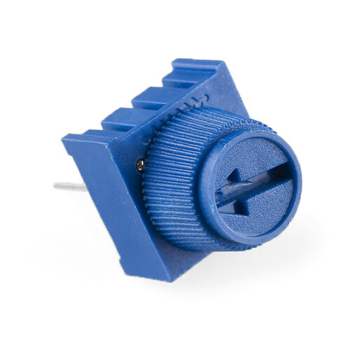
I am working on redesigning a potentiometer to make one of those little blue ones.
I am having an issue with the schematic which I slightly redesigned, somewhat using the one from here: Potentiometer symbol - fritzing forum
It is giving me an error box that says unable to load renderer svg. I have double checked the xml tags but must be missing something if someone doesn’t mind taking a look.
Also, I am mostly developing this for my own use so I haven’t changed the pcb from the original potentiometer but if anyone wants to mess with it to make it correct so that it is a completely functional part, that would be fine with me. 
Here is the part in question:
potentiometer_blue.fzpz (5.1 KB)
That is an easy one. It can’t create a renderer because the part is invalid. It currently looks like this when unzipped:
potentiometer_blue_6aab2d350d5b1432e4a9a2c8379e1b11_1.fzp
potentiometer_blue_6aab2d350d5b1432e4a9a2c8379e1b11_1_breadboard.svg
potentiometer_blue_6aab2d350d5b1432e4a9a2c8379e1b11_1_icon.svg
potentiometer_blue_6aab2d350d5b1432e4a9a2c8379e1b11_1_pcb.svg
potentiometer_blue_6aab2d350d5b1432e4a9a2c8379e1b11_1_schematic.svg
it needs to look like this to be a loadable part.
part.potentiometer_blue_6aab2d350d5b1432e4a9a2c8379e1b11_1.fzp
svg.breadboard.potentiometer_blue_6aab2d350d5b1432e4a9a2c8379e1b11_1_breadboard.svg
svg.icon.potentiometer_blue_6aab2d350d5b1432e4a9a2c8379e1b11_1_icon.svg
svg.pcb.potentiometer_blue_6aab2d350d5b1432e4a9a2c8379e1b11_1_pcb.svg
svg.schematic.potentiometer_blue_6aab2d350d5b1432e4a9a2c8379e1b11_1_schematic.svg
As it stands the loader doesn’t know where to put the files. Once that is done FritzingCheckPart.py has this to say (ignoring the warnings which don’t affect part operation):
Error 77: File
‘svg.schematic.potentiometer_blue_6aab2d350d5b1432e4a9a2c8379e1b11_1_schematic.svg.bak’
At line 178
terminalId connector1terminal-2 can’t be a g as it won’t work.
Error 77: File
‘svg.schematic.potentiometer_blue_6aab2d350d5b1432e4a9a2c8379e1b11_1_schematic.svg.bak’
At line 198
terminalId connector0terminal-old can’t be a g as it won’t work.
as it happens neither of the flagged elements are used so they shouldn’t affect anything, but the layerId does not enclose all the drawing elements so the part won’t export as an image. The pcb svg looks broken, but without a datasheet for the part I can’t fix it. Here is a fixed part (other than pcb).
potentiometer_blue-fixed.fzpz (8.1 KB)
Peter
Thank you so much for your help!
![]()
