Potentiometer symbol

The file naming applies to the fzp files as well. That is the part file name, and needs to stay unique on disk (within the folder), across all families, versions, variants. So for consistency, it should follow much the same format, so that (for example) tht and smd versions of a part are easy to tell apart. Or variants with different colours, voltages, temperatures, or whatever. The fzp file name needs to be as unique as the property names it contains. Using something like “description_property1_property2_etc.fzp” should work. Where it makes sense, use the same field ordering as for the svg file.

From previous research, Fritzing does not seem to be case sensitive for either the names or values of the properties. I would like more consistency, but different capitalizations are treated the same.

That is my expectation as well.

I do not have the full history, but this seems to be used for a couple of reasons. First, if the family is not changed, then the obsolete part is going to be offered as an alternative in Inspector for ‘swapping’ parts. Second, using a consistent pattern for changing the family name makes it easier to match current and obsolete parts when researching the changes history.

This would only be needed for the obsolete files. The active (core) parts are all “current”. Adding the version number when moving to obsolete should work. It would be a good idea to have git do the rename, so that it (git) better tracks the history.

My research says it is not (ever) a problem. From what I can tell, when Fritzing is started, it reads all of the part fzp files (active, obsolete, and user), and associates the module id with the file (full path). When it opens an fzz file, it uses the module id (not file name) stored in the sketch to determine both what the associated file name is, and where it is currently stored. That handles core, user, and obsolete parts all with one process. The name (or location) of the file is not used in the matching process at all.

The same goes for the view files. The svg file that gets used is whatever is specified in the fzp file that gets used based on the module id. That lookup (seems to have) a search order, but I am not clear on which file will be used if the same svg file name exists in both core and obsolete. Will it use the obsolete one (only) if the fzp is also obsolete? I expect that an obsolete part will use a core svg if the svg is not in obsolete, and (probably) a core fzp will use an obsolete svg, if none exist in core. It is just the obsolete fzp with both obsolete and core svg files that is unclear.

An obsolete part needs to contain a “replacedby” tag, which is what is used to tell the user that the part has been replaced, and which part to offer to replace it with. However many steps (update, save, reload cycles) it takes, that tag with the module id is that chain for updating to new(er) versions of a part. The file names have nothing to do with it. “replaced_by” (also) contains a module id, so again, it does not matter if that points to an active, or different obsolete part.

A side thought. It would be more work, but a user part could be “obsoleted” as well. Maybe. If the fzp in the user folder was modified (still in the standard user folder) to have a replacedby tag, pointing to a different module id, Fritzing might offer to do the replacement, instead of needing to do the delete minus, and reconnect all of the wire. The “maybe” is because I think fritzing stores the whole user part in the sketch file. I do not know if will “see” the replacedby tag when a sketch is loaded.
While my track record is poor :slight_smile: I think this is a bad idea. It will probably work from a Fritzing perspective it will leave an incorrect file name in the fzz files the part is part of. For example if we obsolete this 74hc595 and change the fzp to 74HC595_v1.fzp, this reference won’t change in the fz file and will be incorrect (as the file in use will be 74HC595_v1.fzp accessed via the moduleId.)

    <instance moduleIdRef="1a7828b6466fac9fd042221e931124c4" modelIndex="5799" path="C:/fritzing/fritzing.0.9.3b.64.pc/fritzing-parts/core/74HC595.fzp">

I think we would be better to modify the fzp in core with the version number so all new sketches will get that and the old sketches will still have the same file name that is listed in the .fz file so if someone does look at the .fz file (rare I know!) it will still be correct.

Peter
U1

Maintaining the original name when making a part obsolete would be of benefit to those that know enough to extract the fz from the fzz, and read it, but not enough to use a tool like grep to match the moduleid. Or even use a wildcard to look for file names that start with what the fz says the path is. And the path would change anyway. It would now be in /obsolete instead of /core.

As said before AFAIK, fritzing actually only uses the module id to find the parts. It is the only thing safe to use. The location of files is subject to major changes, since the fzz could be opened on a totally different system than it was saved on. Including different OS. Having the actual path in the fz file is only a recent / temporary reference. It is just the last place it saw the part file.

Great. I am looking forward to it.

The fzz has indeed the path of the fzp file, but as reported in the wiki (sketch file): " The moduleIdRef attribute is a reference to a part, in this case, a Red LED." … “The path attribute is only a hint, and no code relies on it.” Therefore, the moduleID is the only important feature for fpz files, not the name of the file.

It makes sense. I guess that in this case, I should use something like pot_trimmer_6mm_tht_3_100mil. I think we should organize the parts by libraries/folders soon, but this is another can of worms that we should not open now.

Nice to know, but I think they can pollute the comboboxes of the properties. At least, I saw that (e.g. “Linear” and “linear” in the track property) when I moved the track property from the parts to the resources.xml file. Thus, affecting the swapping of the parts.

Ok, I will keep doing that and add an issue i the parts repositoty to discuss it. If @KjellM agrees, I will document it in the wiki.

I agree on this for the fpz files (unless the files need to be renamed for improving the consistency of the file names in the repository). However, I would like to avoid this for the svg files. The fpz have the moduleID and therefore are permanently identified. However, the svg files do not have an id and there is no way of knowing the version of the picture without checking the git history. In addition, it will force us to modify all the fpz files of the obsoleted parts (changing the filename of the svg).

I created an issue in the part repository about the obsoleting mechanism https://github.com/fritzing/fritzing-parts/issues/339

The svg files may “need” to be renamed as well to keep them unique. In the case that the same part (svg) gets obsoleted more than once. The fzp already needs to be modified as part of the obsolete process, to add the “replacedby” tag, and to add the “//obsolete//” prefix to the family name. The svg file references could be changed at the same time.

There is a further complication with svg files though. Multiple part files could use the same svg. So obsoleting a part may or may not obsolete the associated svgs. It depends on why the part is being obsoleted. If an svg is obsoleted, then all parts that use that svg, in either core or obsolete can be impacted.

With that, svg and fzp files can be obsoleted independently. What additional changes are needed to other files will depend on the specific case. The goal is to never ‘break’ any existing fzz sketch files that are using the part (fzp), or parts that use the svg.

The obsolete process needs to include searching all parts for references to any obsoleted svg files, with possible changes to those parts as well. That is never going to be 100% accurate, because custom (user) parts can be referencing the core svg files as well.

If we rename the old svg files, we will break all custom parts that use the old svgs. If we move the old svg file to the obsolete folder and we do not rename it (we rename the updated or new svg file), we will not break custom parts.

Correct, though the search should still be done. To detect other parts that should maybe be using the updated svg as well.

Yes, I agree. However this is the opposite that we have suggested for the fpz files, see our previous discussion:

I wonder if it would be also better to copy the old fpz files to the obsolete folder without renaming them and rename the updated versions of the core. Thus, we will have the same procedure for svg files and fpz files…

Please check the script fritzing-parts/obsolete.py at develop · fritzing/fritzing-parts · GitHub for obsoleting a part. It should be run before starting work on the new part, in fact it will create the replacement part based on the obsoleted one. Of course, if you already made changes, they can be copied over to the new part.

If there are any problems or questions about this, please open an issue in fritzing-parts.

OK, I am making progress. I have updated the potentiometers with the new schematic symbol, the force resistive sensors with the rheostat symbol and the textile parts with the pot and rhostat symbol. Thus, no parts use the old potentiometer symbol anymore and just the thermistors still use the thermistor symbol. It would be nice to update it to have all the symbols more homogenous, but it can be done later as it is the right symbol (just bigger than the new symbols).

The files can be seen in my repository: updated the potentiometer and rheostat symbols in the schematic view … · failiz/fritzing-parts@23bedb1 · GitHub

I have tested the obsolete mechanism and it works well.

@vanepp , I only need an updated version of the potentiometer with a switch for the schematic view. With that one, the most pressing fixes would be done. Of course, the other fixes to the BB and PCB views are welcome. In any case, no rush and I hope that you recovery is going well!

My wrist is healing slower than I hoped (probably because I live alone and thus have to keep using it just to survive!) but it is getting better. While we are doing changes I would like to do as many at once as we can, essentially changing them in to the final configuration of parts. I have done the 6mm and 12mm pots with the changes I think they need. I have detailed the changes I made below

6mm-trimpot

pcb

scale correct 10.41667
units correct in
add pot outline and adjuster screw to silkscreen.
check pad positioning against data sheet (correct)
convert silkscreen color from white to black. 
hole size is 1.04mm against recommended 0.09mm, left at 1.04mm. 

schematic

replace with the new schematic. 

breadboard

scale 1.04167 change to 10.41667
units correct in
ungroup and rescale. 
check size, correct 6.3mm
move connectors in order to the bottom of the svg
regroup, change id to breadboard and save. 

fzp

change Fritzing version to 0.9.9
add note to author saying I changed this on Jan 2022
Change title to 6mm Trimmer Potentiometer from Trimmer Potentiometer
modify icon layerId to reuse breadboard svg
add url that I took the specs from for this part

run through FritzingCheckPart.py to check for problems and test in Fritizng.

done.

Put in this .fzpz file as a new part so it can be loaded independently to compare to the current one.

6mm-trimpot.fzpz (6.9 KB)

12mm-trim-pot

 This one is more of a problem. They don't appear to make these anymore in that a google search for 12mm trim pot doesn't turn up any parts to buy (or a data sheet to look at for sizes!) It may be this is one of the parts that should be obsoleted with no replacement (noted as a TBD in the obsolete script Kjell mentioned) but I'm not sure of that, maybe I am just not searching correctly. 

breadboard

scale 1.04167 change to 10.41667
units correct in
ungroup and rescale. 

Can not find any 12mm trim pots in google search so increase size of breadboard image (currently identical to the 6mm pot) to match the outline in pcb view. Move the wiper up 0.1in to match the position in pcb.
Move connectors in order to the bottom of the svg
regroup, change id to breadboard and save.

schematic

replace with the new schematic. 

pcb

Scale is correct 10.41667
Units correct in
Assume (as I can't find a data sheet to verify!) pcb is correct and leave as is except change silkscreen from white to black. 
Change pad to pin (pad is typically for SMD pin is more common for THT!)
delete unused keepout, soldermask and outline groups.  

fzp

change Fritzing version to 0.9.9
add note to author saying I changed this on Jan 2022
Change title to 6mm Trimmer Potentiometer from Trimmer Potentiometer
modify icon layerId to reuse breadboard svg

<iconView>
  <layers image="breadboard/12mm-trimpot_da06bb58704f8057ad9fa2ada8b4e85c_1_breadboard.svg">
    <layer layerId="icon"/>
  </layers>
</iconView>

for all connectors substitute pin for pad (only affects pcb layer!)

run through FritzingCheckPart.py to check for problems and test in Fritizng.

done

12mm-trim-pot.fzpz (7.1 KB)

Some of the changes depend on the rest of the community agreeing with the changes I will be suggesting when I manage to get the document finished which is currently going slowly because typing is currently painful! I’ll take a look at the 6mm and 12mm parts in your repo and point out the additional changes I think should be made to them hopefully fairly quickly.

edit

Here is a copy of the requested pot with switch. Note there are a fair number of changes than only the schematic svg. Again is is a new part and can be loaded beside the current version for comparison. Here is a list of the changes

Dial Potentiometer with switch

breadboard

drawing elements outside the layerId
change scale from 0.75 to 10.4166
dim in in (correct) 
remove terminalId as unneeded (the pin is fine.)
move connectors to the bottom of the svg.

icon

replace with the breadboard svg in the fzp file and delete the icon svg.

schematic

replace the pot with the new pot svg and add the switch (moving the switch to the other side of the pot.) Reduce the size of the switch by .1 in

rescale from 0.75 to 10.41667
dim in (correct)

change font sizes to 25px and line and text colors to #555555

pcb

rescale from 0.75 to 10.41667
dim in (correct) 
change silkscreen color from white to black. 
Replace partial outline with a circle (as the knob is circular) so the silkscreen reflects the actual size of the knob. Adjust the swith to be in the center of the switch pads. 

fzp

change Fritzing version to 0.9.9
replace icon image layer with breadboard
move connector3 and connector4 after connector2 so the pins are in sequence as they should be.
Remove the terminalId definitions from breadboard in all pins (as we removed them in the breadboard svg!)

then run through FritzingCheckPart.py and test in Fritzing to make sure all is well (do the gerber output as well to make sure gerber is OK!)

Dial Potentiometer with switch.fzpz (5.9 KB)

Peter

Great. I have updated the parts. There is a small problem in the 12mmTrimmer and the dialPot.

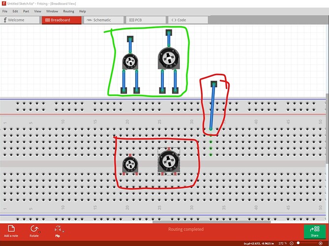
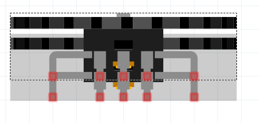
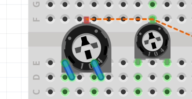
In the 12mmTrimmer, after upgrading a part that is attached to a breadboard, the part gets missaligned of the grid, see below (left upgraded part, right a 6mmTrimer for comparison):
image
Is there s 0.05inches offset in the svg of this part?

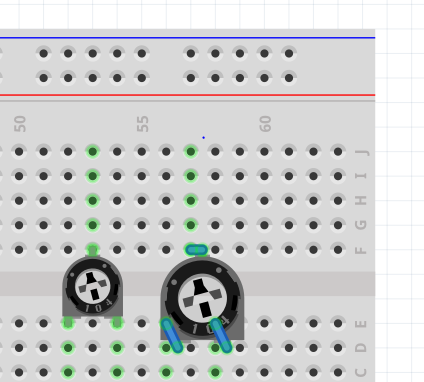
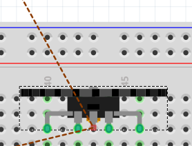
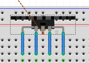
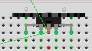
In the dial with switch, the central pin gets disconnected from the breadboard after updating it, see below?
image
I am not sure what happen here. Any ideas?

Please, use my already modified fpz files for the other parts. It saves some time :slight_smile:

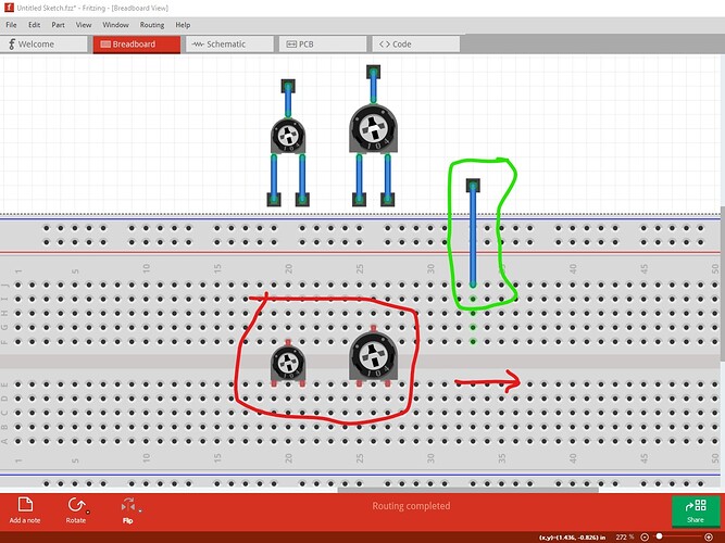
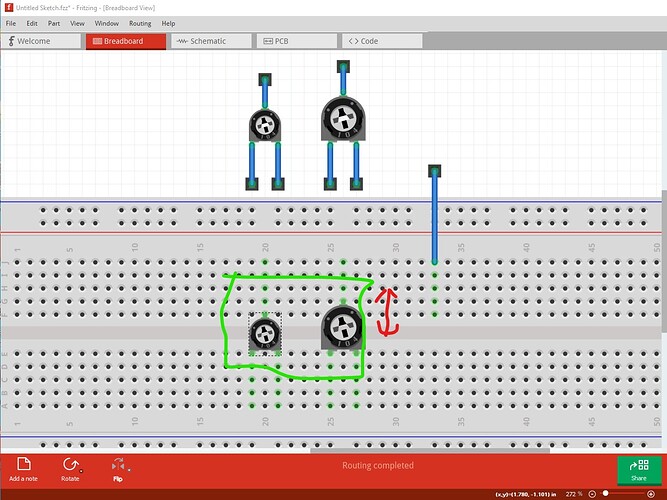
The first one is a bug with breadboard placement not the parts. This is the old and new 12mm parts and the breadboard after a clean start of Fritzing. Note the breadboard is 0.05in offset from the grid lines in X!

and the parts which connect correctly to the connector at the top do not connect to breadboard (because breadboard is misaligned!) and the connector on the grid has an offset to the breadboard connection. I then move the breadboard one position left and it snaps to the grid, but the parts still don’t connect as the breadboard is female connectors and only movement of the male connector makes a connection occur.

moving the two pots up then down one pin in Y makes the breadboard connect correctly.

I don’t know what is happening with the second issue. The part appears to be correct. The pins are exactly on 0.1in boundaries in the breadboard svg. I did remove the breadboard terminalIds, but they were only on the outer two switch pins not the three center pins, so I don’t know why it doesn’t connect. I’ll run through the parts in your repository and make any changes I think should be made as I get time.

Peter

OK, thanks for the input. I had some time to look into these. I think that both problems are caused by different sizes of the images.

I cannot see this in my computer. The breadboard is aligned to the grid before updating the parts and before updating them.

In the first case, the problem is that the part is now bigger and Fritzing takes the top left corner of the part as the origin of the part. As discussed by @microMerlin here, it would be nice to expand the part format to specify which connector in the part to use as the ‘origin’, to align to the grid. Thus, we could specify that the top pin is the origin and the part would be modified correctly in most cases (The bottom pins would go down but this is not a problem in breadboards).

However, there is (maybe) a bug of the swapping mechanism. Now it adds wires to keep the connections of the bottom connectors, which is ok. However, the top connector of the potentiometer does not get a wire, which I think is a bug. See below:
image

When swapping a new of the potentiometers (trimmer-6mm) to a trimmer-12mm through the inspector pane, three wires are added, see below:
image
So, it looks like this is a bug of the swapping mechanism when there are ratsnets. I will add a bug in the bug tracker.

Regarding the second one, the cause is the same. It looks like the new part has a offset (in the vertical axis) that the old one does not have. Observe the following pictures where the one of them is selected and the other is highlighted in grey:
In the picture below, the horizontal alignment is correct (the old part is at the bottom and the new one at the top) :
image
In the picture below, it seems that there is an offset in the vertical alignment (the old part is at the left and the new one at the right) :
image

That offset is forcing to use wires to connect the connectors of the part with the breadboard when it is not necessary as in this case the part should not change dimensions. The same bug in the obsoleting mechanism as before is causing that there are only four wires instead of fives. The picture below shows the part after the upgrade:
image

If we drag it, we can observe the wires:

image

So, I think the trimmer-12mm svg is correct and it is the user who needs to handle this. But I think that the dial pot svg should be fixed to not require fixing the breadboard view after the upgrade of the parts.

I was just placing the parts and for me (on Win10 Fritzing 0.9.9) the breadboard at initial load is usually 0.05 offset in X.

Yes this is true. I think (but don’t have proof) that it is even worse in that not always is the same pin used to snap to the grid. I have seen cases were there are pins not on the grid (such as the Uno) where which pin aligns to the grid changes on different loads of the same part. So I agree a common pin as the origin would be a great improvement. I don’t think this is under consideration though as the issue has been closed.

That was likely caused (although I haven’t checked!) because the origin of the original part was not X 0 Y 0. I normally do (in Inkscape!) and Edit->select all, then Edit->resize page to selection to set the origin X and Y to 0 0. If that is not done there will be an offset in Fritzing which is undesirable. I would like to see this as one of the requirements of part svgs for this reason.

Peter

Adding resources.xml to the mix could have changed the ‘rules’. It was not part of what I looked at before. Without that, I did not see any doubled entries in inspector, even when there was a mix of case in the fzp files.

I assume that the “upgrading” was done through Fritzing offering a replacement for an obsoleted part. The automatic replacement there should position the new part based on one of the connectors common to both the old and new parts. However, as vanepp suggests, it could be getting mixed up with the origin of the svg file.

Are both the old and the new svg connector pins at 0.1 in spacing? If the new is but the old was slightly off, I think you might see this symptom. Earlier testing trying to fix a part with (among other things) small spacing issues through obsolete and update found that if the position of the new and old connector pins where not quite close enough, Fritzing would not automatically connect them. Even though a move of the part, away and back, would then connect. Though what I remember, it should have added a wire to compensate as seen in other samples.

The logic used for swapping parts through inspector is (seems to be) quite different from what is used for obsolete and update to new versions. Both seem to ignore any grid settings. (At least) Inspector uses the graphic origin of the svg, then adds (or move ends of) wires or ratsnest. With the size change, based on the graphic origin, the connectors moved away from the original breaboard holes, so wires were added. The wires on the bottom pins connected to the origial breadboard holes. The logic is not smart enough to notice that the other holes are closer and equivalent.

Is it possible that the original smaller part had (invisible because zero length) wires from the pins to the breadboard holes? Without that, I would have expected ratsnest instead of wires.

I do the equivalent. Part SVG files should have the origin at 0,0. I remember discusion of problems that seemed to be tied to other cases. I have not seen them, because my process always ends up with 0,0 origins.

Related to some of this, remember that some breadboards are not fully on the 0.1 in grid either. The connectors for the bus lines are offset from the grid used for the groups in the middle. For some breadboards. Combined with newly placed parts randomly picking a connector to use to align to the current grid, that means that the breadboard can be “off grid” from what is expected. Combine, again, with the way inspector seems to use the graphic origin when switching parts, and the breadboard can be totally off the grid alignment. My automatic process is to move (jiggle, all views) parts (including breadboard) after switching. To get aligned to grid again. For breadboards, there is an extra check, to make sure that the “main” holes align to the grid. If they do not, change grid to 0.05 spacing, reposition breadboard by 0.05 in, lock the breadboard position, change grid back to 0.1 in spacing. Then delete any bogus breadboard view wires and jiggle the parts to get them to reconnect. Usually I move all parts off the breadboard before changing the breadboard. Cleanup is easier.

I have opened an issue in the bug tracker. If you know how to replicate the part that changes its alignment on different loads, feel free to post it.

It could be. First, I changed all the properties to start with a lower case in the resources.xml and in the new parts. This worked well for new parts. However, when using old parts and going through the obsoleting mechanism, the parts got their old properties (which started with an upper case letter). So, probably Fritzing is not handling well this corner case. Finally, I left all the properties starting with an upper case letter (both in resources.xml and properties).

Yes, I used the upgrade menu that appears after you open a sketch with obsolete parts. I did not see that Fritzing positions the parts based on the connectors. It always keeps the upper left corner of the svg file.

This seems a bug in the swapping mechanism. I open a bug here

At the beginning, I thought that it was a bug in the obsoleting mechanism, but I could replicate this bug when swapping a part. So, I just think that the obsoleting mechanism is just triggering a swap.

Yes, I agree that the svgs should start at 0,0. However, this fix in the part will cause to add wires in the breadboard and (likely) remove wires from the schematic view, changing a lot the sketch. I am wondering if this fix is worth it right now. Would it cause severe problems? I can see three options. The first one would be to leave the offset in this part to do not mess the sketches of the users. Potentiometers are common parts and it could be painful to clean the sketch after the update. Another option would be to comment the replacedby attribute in the old part. This would not trigger the update mechanism. We could uncomment it once the origin in the connectors feature is implemented and the bug with the sapping mechanism fixed. Thus, the new potentiometers added to the sketch will use the new parts and the sketches with old potentiometers will still use the old parts. Finally, we could fix the part and force the users to clean up the sketch after the upgrade. If so, I think it would a good idea to specify which parts will be upgraded, see issue here. @KjellM , what do you think is the best strategy?

I think the new schematic symbols and the correct 12mm trimmer breadboard symbol are good improvements. But we don’t need to fix existing circuits, maybe the look is not perfect, but they are not broken. We should obsolete the current parts, replace them with the new ones, but don’t trigger the obsoletion mechanism for existing circuits. This should be possible by not adding a replacedby marker to the obsoleted parts.

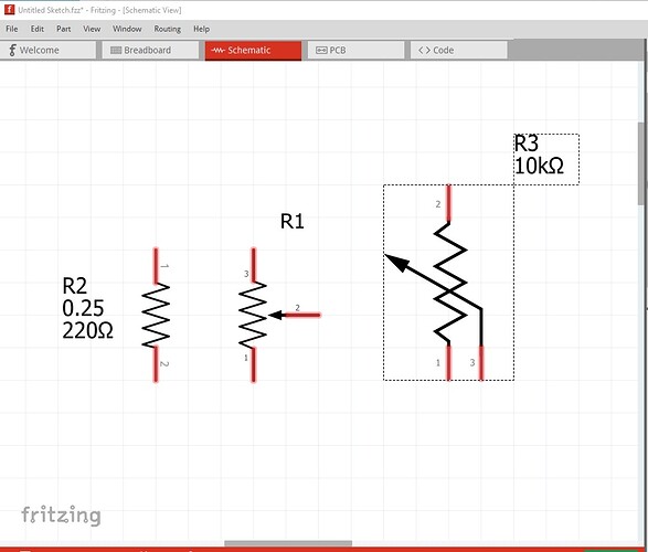
PS. Is it possible to keep the schematic symbol symmetric? Either by using a height of 4 * standard grid, as the current symbol, or by using 2 * standard grid, like the resistors. Then the wiper could be connected exactly in the middle.

I like this suggestion! It avoids the hassle of updating previous sketches (requiring the user do the upgrade manually if they want to mix new pots in to an old circuit) and thus avoids the pin placement issues. I think we do want to consider the pin positioning issues at some point to make obsoleting work better though! We can then update all the svgs to meet the graphic standards going forward as well!

The current new schematic (R1 in this image) matches the standard resistor (and thus is 0.1in less high than the original) it is 4x3 rather than 4x4 (and thus not symmetrical in X but I think does what you want). Would you like the wiper moved out 0.1in in X? I think all that does is waste space in schematic though. Here R2 is a standard resistor, R1 is the new 12mm pot (which doesn’t seem to be made anymore and perhaps should be obsoleted with no replacement?) and R3 is the current 12mm pot. The 6mm trimpot seems to be the only one sold any more.

Peter