This is a continuation of
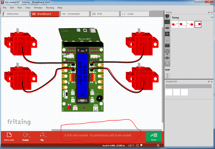
This demonstrates the intended use of the family and variant properties in the fzp file. The purpose of the family and variant fields are to allow the user via the variant field in Inspector (or sometimes fritzing for its self I think) to swap parts. For that to work all the parts in a family need to have the same number of connectors which connect to the same pin on the part (although as we see here, their position may be different between variants.) In this example I have a Yahboom super:bit interface board and 4 DC motor variants that connect to the super:bit board. The intended use looks like this:
here all 4 motors are connected to their appropriate connector on the super:bit. This is the .fzz file that the following images refer to so you can load this .fzz in to Fritzing and try the changes below for yourself and see the effect of changing the variant values. There are 4 motor parts here (they and the super-bit part will be in the temp parts bin when the not-routed.fzz file below is loaded in to Fritzing):
not-routed.fzz (79.4 KB)
which will have in the temp parts bin:
yahboom-red-motor-left-top.fzpz
yahboom-red-motor-left-bottom.fzpz
yahboom-red-motor-right-top.fzpz
yahboom-red-motor-right-bottom.fzpz
in all 4 cases the family property is
<property name="family">yahboom red dc motor</property>
but each part has a different variant property (according to motor name / position):
<property name="variant">variant left-top</property>

<property name="variant">variant left-bottom</property>

<property name="variant">variant right-top</property>

<property name="variant">variant right-bottom</property>
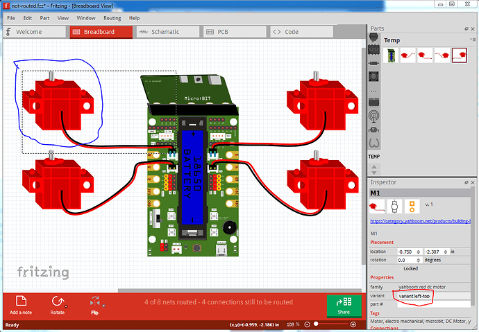
(note: the “variant” that starts each property is required, if it is omitted the variant will display in inspector but you can’t select the other values in the pull down menu because the menu is not instantiated.) If one of the variants has more or less connectors defined, you will get the “red square because a defined connection is missing” indication in the various views so you need to be careful that all the parts in a family really are interchangeable. There currently is no testing to insure this, but I intend to add such a check to the parts checking script. So that said lets try changing motor 1 from its correct variant of “variant left top” as shown here:
to each of the other variants in turn, this is left bottom:
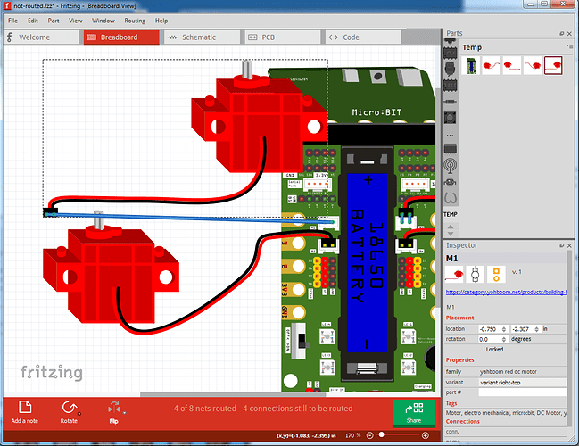
Note because there were wires connection this motor to the super:bit they have been stretched to connect to the new position of the connector. If I now change motor 2 (which does not have wires connecting it to the super:bit), it should disconnect, as it is no longer connecting, but in fact does not (which is likely a bug!), instead the rats nest line in schematic remains and clicking on the motor connector lights the pin on the super-bit yellow indicating a connection (and the routed connections number has not changed.) Changing motor 2 back to bottom left and motor1 to “variant right top” again stretches the wires to the new connector position:
and similarly changing motor 1 to right bottom produces this effect:
This concludes the family / variant howto. Next is the suppressing pcb layer howto available here:


