This is a continuation of
This demonstrates (with a completely new part) how to convert a minimal 2-D image part (a Yahboom lego motor in this case) in to a simulated 3-D part in breadboard via Inkscape. We will start from this part which is a basic 2-d representation of the part using nothing more than rectangles that looks like this:
svg.breadboard.yahboom-red-motor_1_breadboard-starting-2d.svg.fzp (4.3 KB)
(you need to remove the trailing .fzp from this to get the .svg file which this actually is due to forum limitations)
to this finished part. I will only cover breadboard here, schematic and pcb are ordinary, and can be created by following parts 1 to 4 in this series.
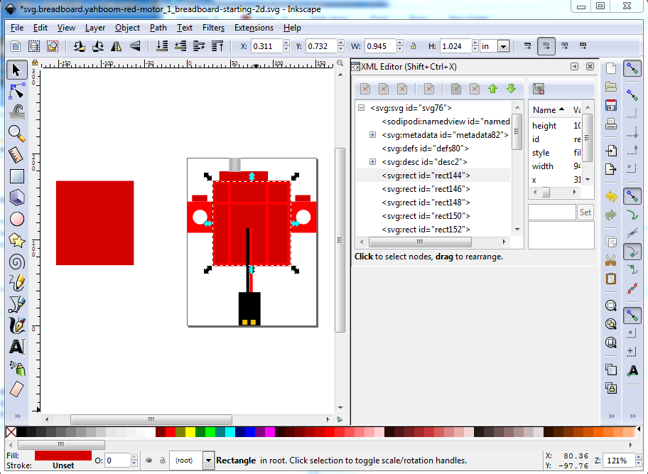
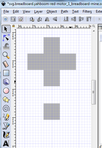
Start by copying svg.breadboard.yahboom-red-motor_1_breadboard-starting-2d.svg in to svg.breadboard.yahboom-red-motor_1_breadboard.svg then edit svg.breadboard.yahboom-red-motor_1_breadboard.svg in Inkscape and duplicate the base rectangle and move it left in x to clear the part. This is the starting template that we are going to skew, scale and recolor to make the 3-d image. First, though make sure scale stroke width is disabled (we don’t want that changing the dimensions as we try and align things!):
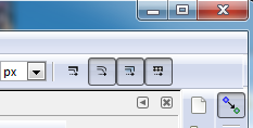
Then shut off snap to grid:
because we want to be able to scale exactly, not necessarily to the grid in this case.
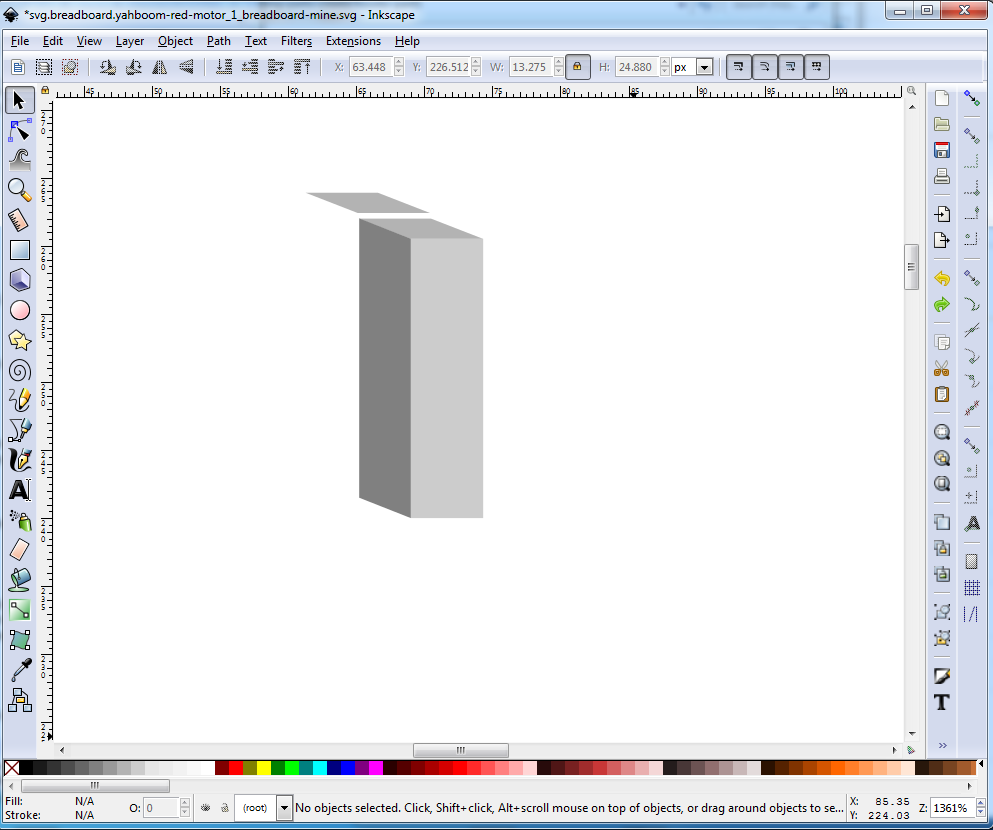
Then duplicate and move the the left the base rectangle like this:
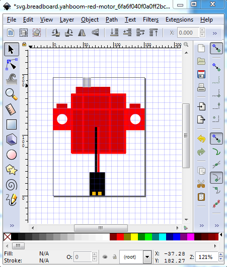
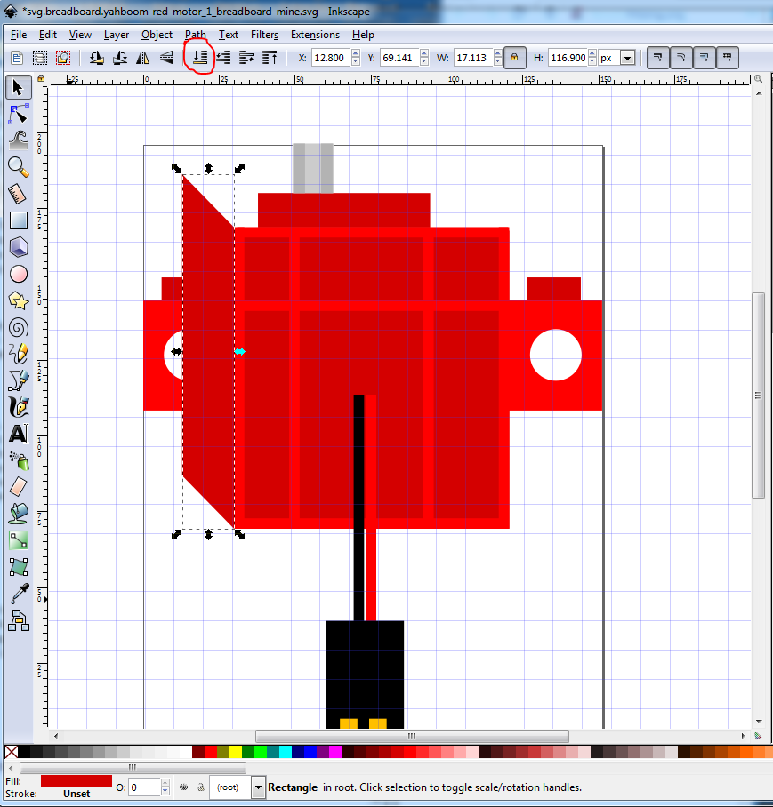
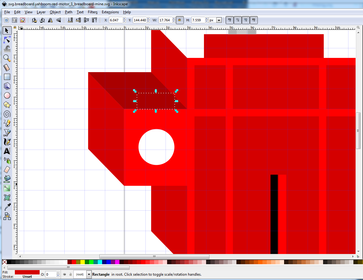
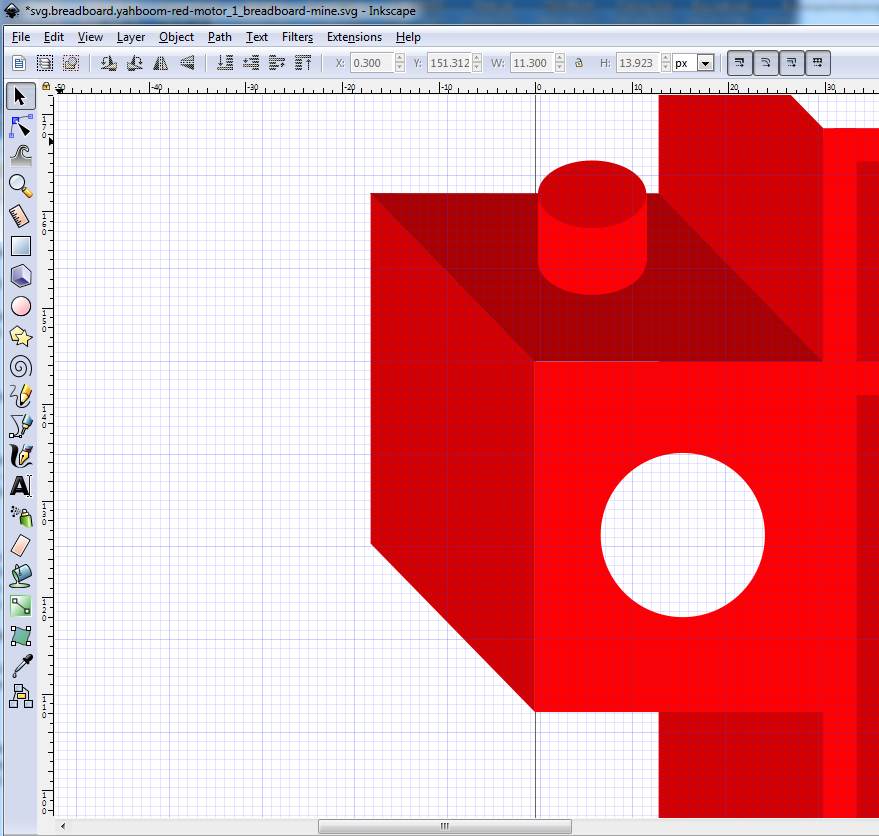
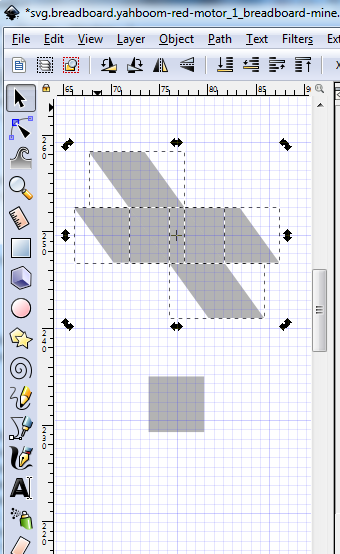
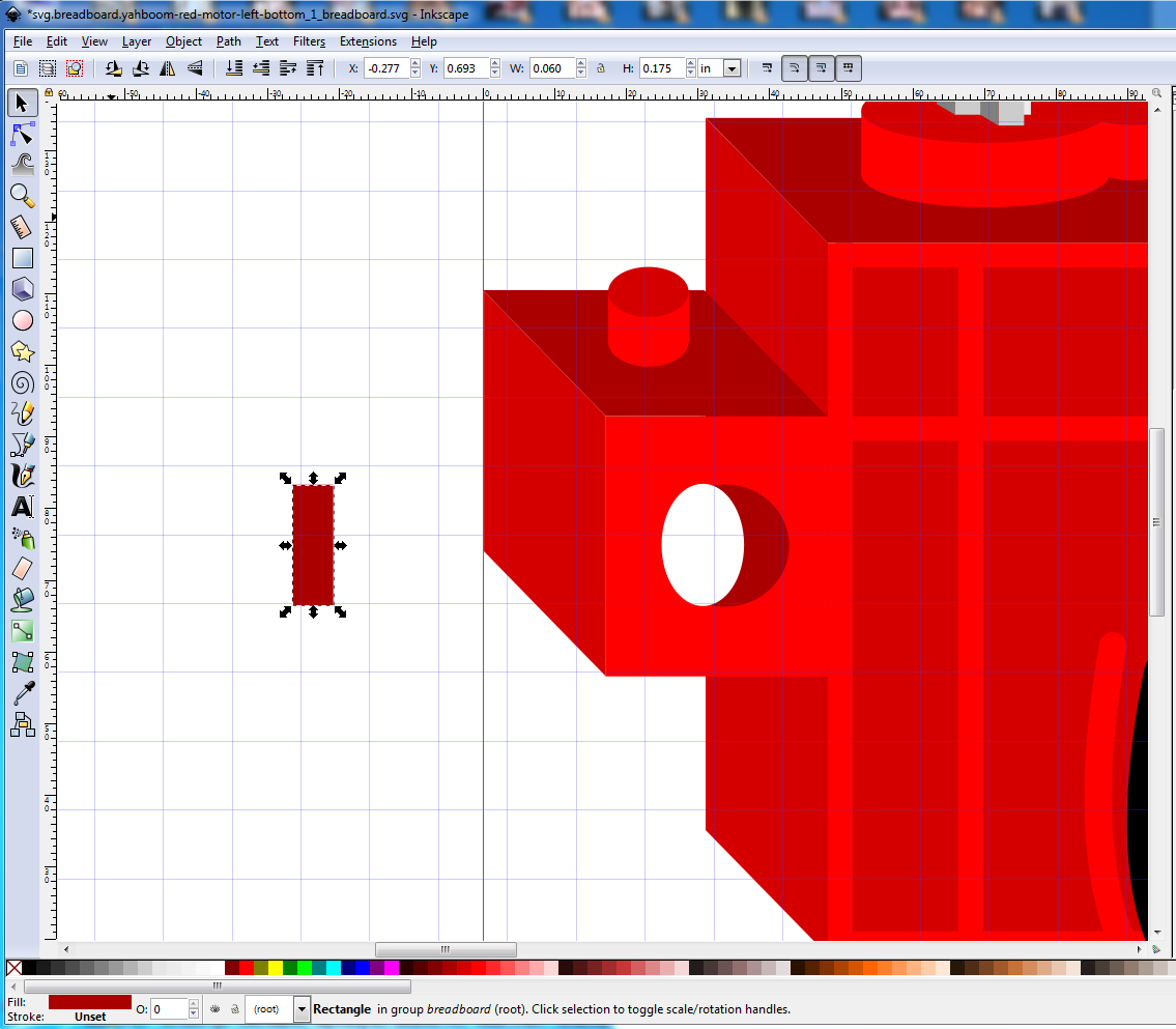
We want to end up with the skewed image to the right of the rectangle (to make the side of the body), to do that we first need to scale the initial rectangle narrower in x. We can do that either by reducing the width in the tool bar, or as in this case by clicking on the rectangle and click and drag the scale arrow (circled in blue here) towards the right til the rectangle is the right size (just take a guess at the size, you will need to iterate these moves until the skewed rectangle is the correct shape which is why to use the scale and skew arrows rather than the toolbar.)
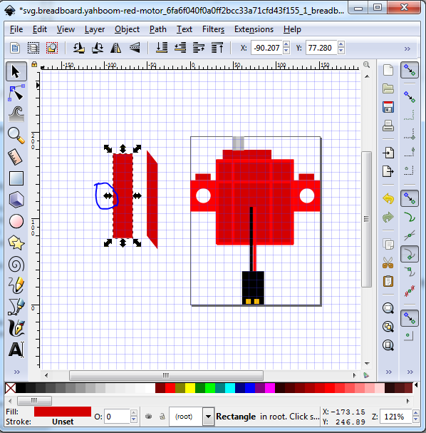
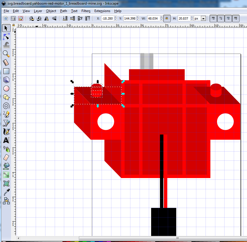
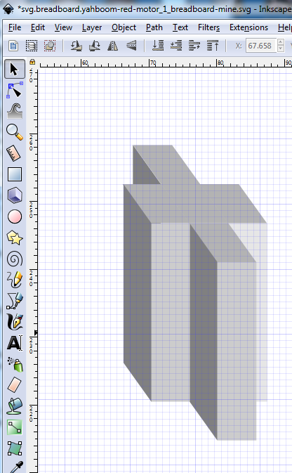
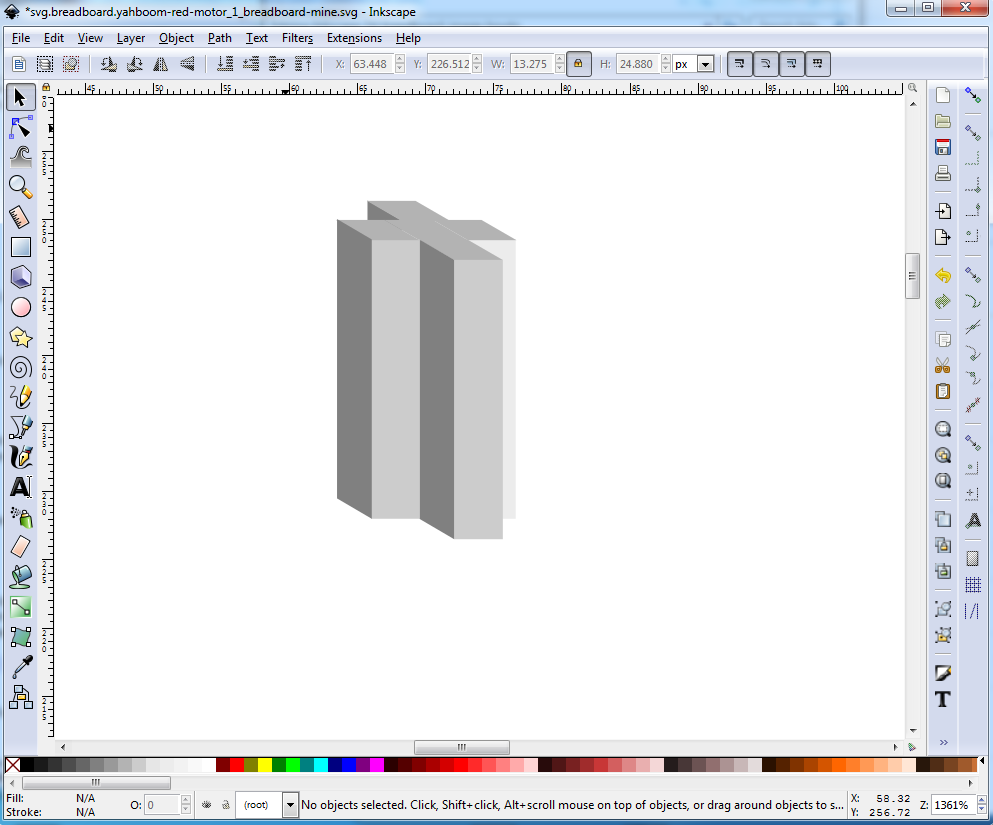
Now click on the duplicated rectangle. The scale arrows will change to skew arrows like this:

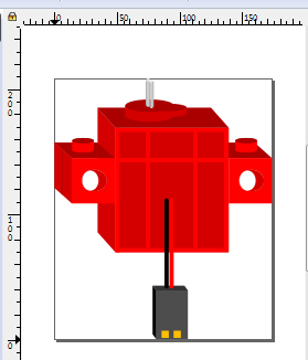
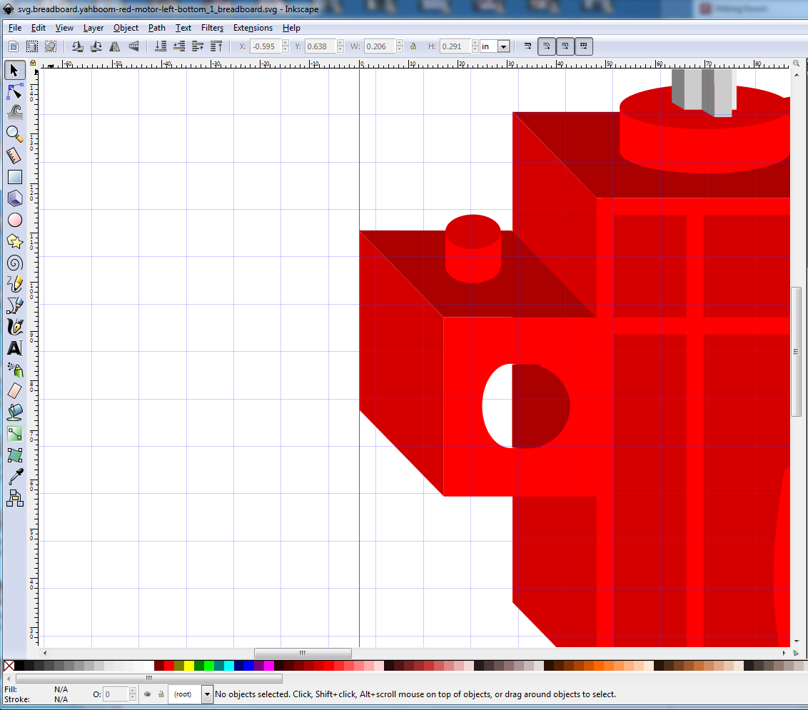
click and drag the skew arrow circled in red towards the top of the screen. The rectangle will skew til it looks like the image. Now click and drag the skewed rectangle you just created til its bottom edge is aligned exactly with the bottom edge of the base rectangle like this:

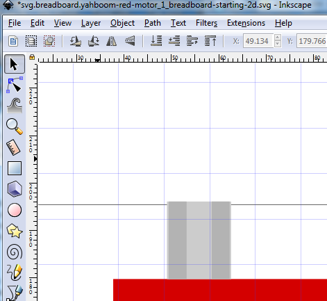
At this point you can see the 3-d image starting to appear. The rest of this is pretty much repeating these steps (with lots of trial and error to get it looking right!) The other thing we are going to do but haven’t yet, is to change the color slightly to make panels that should go back darker in the same color (to go back) or lighter (to come forward.) Here is an example from the motor shaft in the original svg. Note the center rectangle in the shaft that is a lighter silver color to indicate the spline of the shaft:
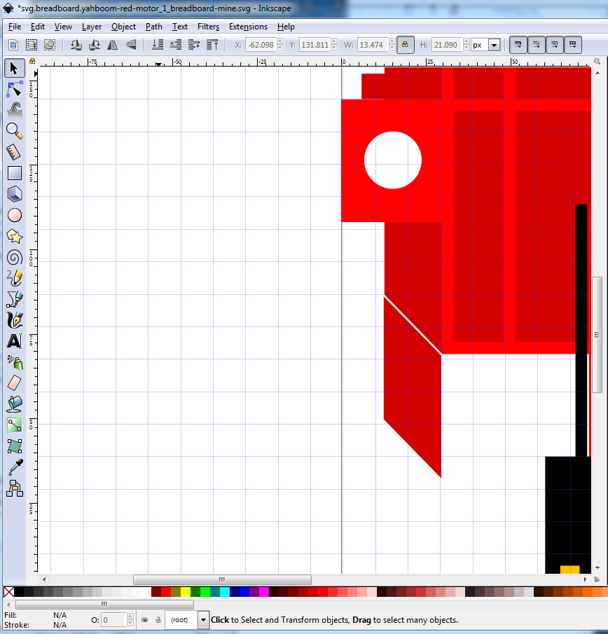
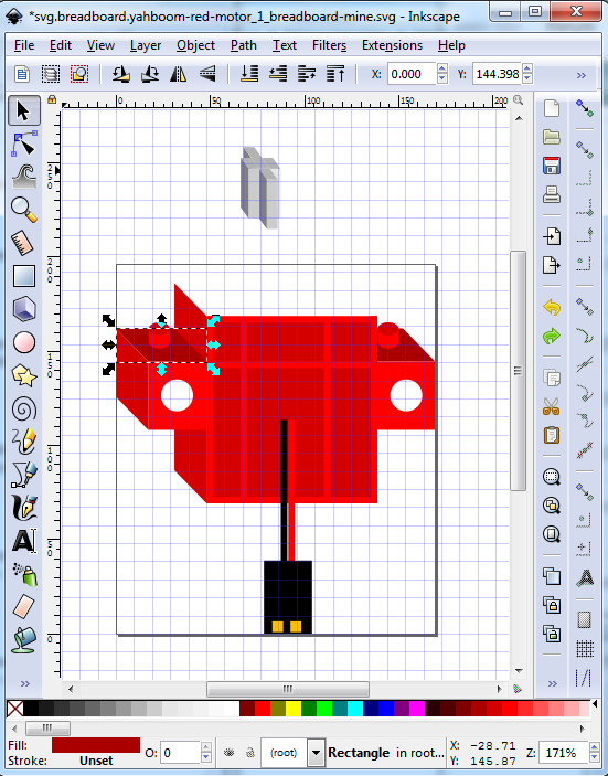
but that is for later. For now we need to align and scale the skewed rectangle, so click and drag the skewed rectangle til there is a bit of white showing between it and the base rectangle like this, then select the the base rectangle, copy its y coord from the tool bar and use that to set the y coor of the skewed rectangle so they both start at the same y position like this:
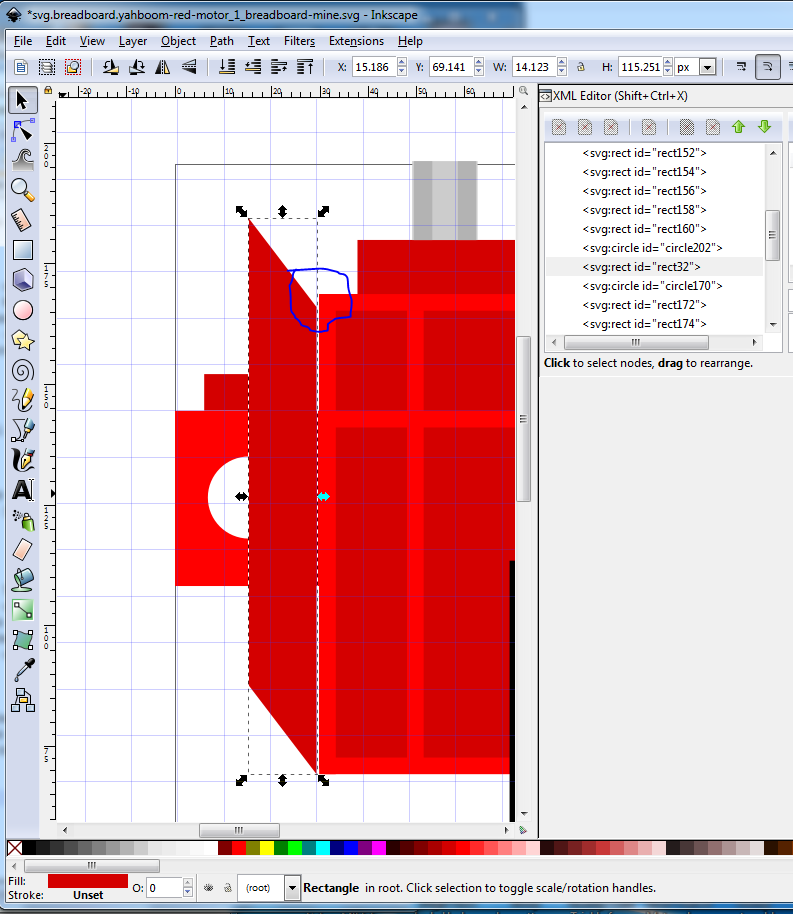
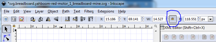
where the rectangle (not selected here) is also y 69.141. Note that although we started from an identical sized rectangle the skew has made the leading edge shorter (outlined in blue) so we need to increase the height either with the tool bar or by dragging the y scale arrow on the top. But before doing that, we want to set the height/width lock, because if we do not, increasing the height will also increase the skew (as the width remains constant), with the lock set the width will scale to keep the skew constant as we increase the height which is what we want, the default is unlocked, because normally that is what we want.

so change that to locked for now.
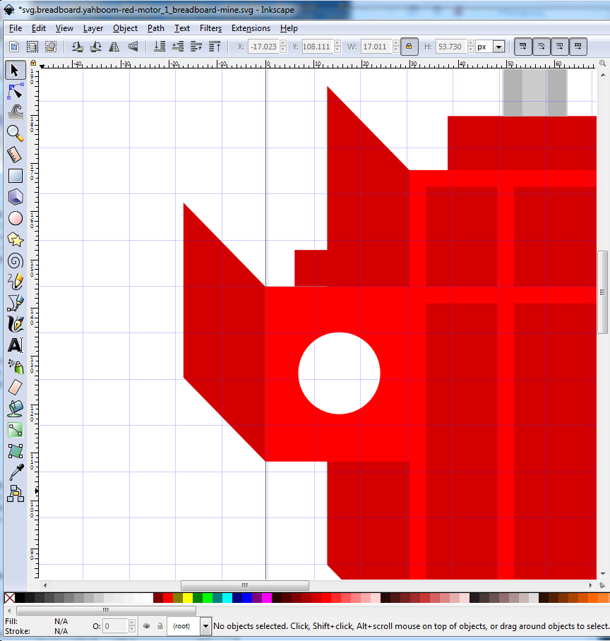
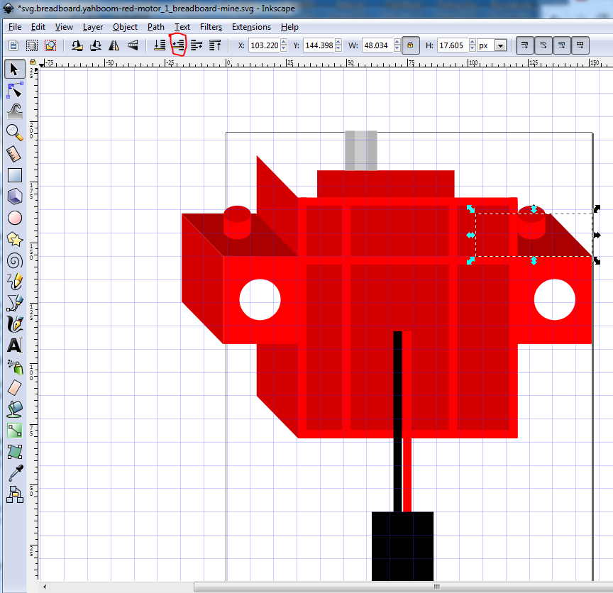
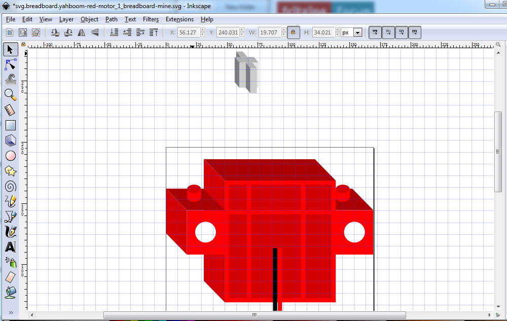
Now we want to raise the top edge til it just meets the top edge of the base rectangle like this (the width will get slightly larger as well to keep the skew the same.) As noted you can either click and drag the top select bar to move the top edge higher, or (as I did) manually change the height value in the tool bar to bring the top edge of the skewed rectangle to meet the top of the rectangle like this:

If your svg looks like this instead of the above:
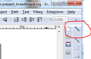
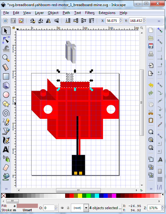
You need to select the skewed rectangle and move it to the top of xml editor by clicking the tool bar button circled in red. Now we are going to repeat what we just did with the tab on the side of the skewed rectangle. So duplicate the tab rectangle and move it to below the skewed rectangle, then change its color to match the skewed rectangle, and leaving the height identical to the tab, change the width and skew to match the skewed rectangle like this (w and h are still locked here):
Then move it in to position as you did with the skewed rectangle to produce this:
Now duplicate the front of the tab yet again, move it up a bit, set its color a shade or two darker then skew it to match the skew of the just created side piece like this:

Now you have to iterate the height / width / skew of the new piece until if fits exactly in to the space like this:
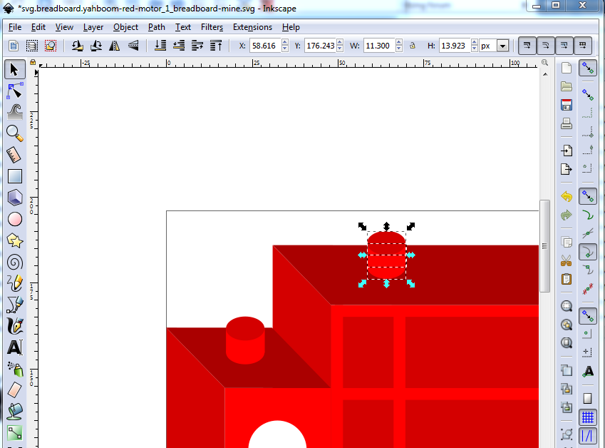
Of note here is the pin on the top is still present (I have selected it here) but is obsucured by the top. Since we are going to replace this with a circular column, just delete it at this point. To start making the pin on the top, create an ellipse with the circle tool:
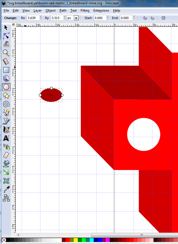
then duplicate it, and make a rectangle as well. Now from the tool bar, set the x coord, width and height of all three (the two ellipses and the rectangle) to be identical. In my case the color was already the red of the top of the tab, if yours is not, set it to that. Set the color of the rectangle and bottom ellipse on shade lighter in red (so they won’t fade in to the tab when moved there later.) It should look like this:
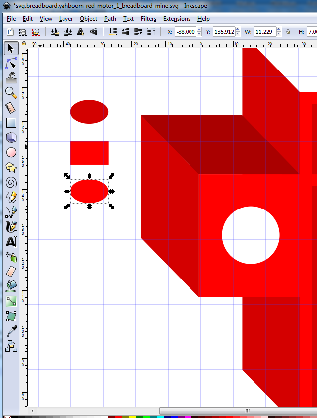
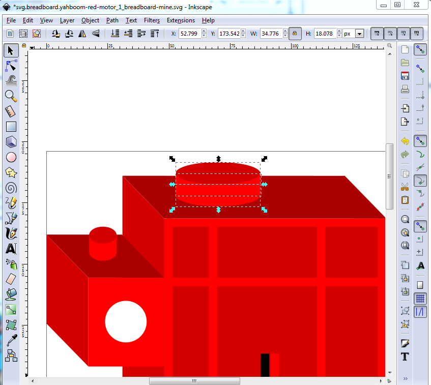
Now move the rectangle down in y til its bottom edge is at the center of the bottom ellipse. Move the top ellipse down in y til its center is at the top of the rectangle like this:
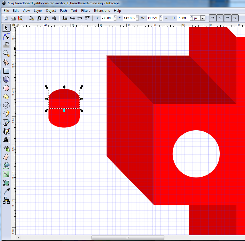
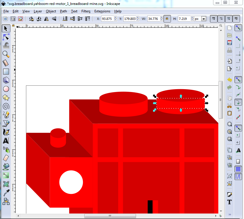
Here we see we have a half peg (because of the order I created the ellipses.) Since I want a full peg I need to move the top ellipse up a couple of times until it is below the rectangle and thus fully visible (click the icon on the tool bar until the full top ellipse appears.) It should then look like this:

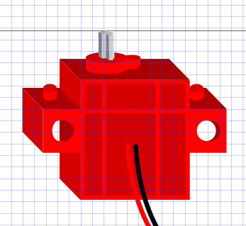
Now select the entire pin and move it in x and y to its final position on the top of the tab. (this motor is intended to be used with Lego blocks to build robots, thus the pin on a tab) like this:
Now let laziness rule and duplicate the entire construct and move it in x til it is on the opposite edge (which wants to be identical.) Note that the dark top is too high in the hierarchy and wants to move down:
Note that the dark top is too high in the hierarchy and wants to move down (by clicking the circled tool bar icon til the base is hidden like this):
Now will move on to making the motor shaft. I struggled with this, and tried a few unsuccessful things before going back to basics. The shaft is 5 squares like this which is the secret to making it (here split apart to show the 5 squares):
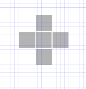
Then in document properties->grids set x and y offset from 0.05in to 0. In the tool bar set units to in then set the width and height of each square to 0.06in (as that is the width of each square) then move the center square to x 0.770in y 2.570in to be centered on x and y major grid lines (note actually doing this leaves a white line at the join between the left and center squares, to correct that I had to change dimensions to px and set left square x to 68.200px and center square x to 73.900px which translates to x 0.770in y 2.570in but without the white line between the squares due to floating point round off. Sometimes you have to get more precise than bare inches will give you to get what you need. Here 0.710in runs from 68.111px to 68.207px, so a value of 68.16 is good (right in the middle of the range). 68.111 comes up as 0.711in. So for extreme accuracy, use dimensions in px (for Inkscape 0.9.2.4 in use here,there are 96px per inch) In this case I used the drag arrows exactly on the grid lines to position the squares so there are no white lines between squares like this:

That gives me the top of the shaft. Now I need to add the lines down for the shaft splines. So duplicate the bottome square and move it down in y like this:
Then select the entire top of the shaft, set lock on w and height then skew the top of the shaft like this:
Now we can use the still straight square to make (and color) the shaft like this: drag the bottom scale bar to increase the size of the rectangle and change its color one size lighter:
Now duplicate the rectangle and then make it two steps darker (the top bar is one step darker!) to stand out from the top. Skew it to match the side of the skewed arm by scaling it inwards til they are the same size, iterate between scale and skew til it is correct like this:

Now the laziness principle takes hold and we duplicate the square column and move it to the places that need a square column, and duplicate the skewed column and copy it to where we need skewed columns which looks like this (which currently looks more like modern art than the shaft!):
To correct that we need to select the various new pieces and move them lower til the parts that should cover them do so and when needed change the color a shade lighter or darker to differentiate between two columns, leaving us with the final shaft:
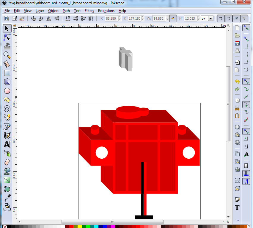
Now we need to deal with the oddly shaped motor shaft bump on the top. First delete the two-d versions as unneeded (the grey piece is the shaft above it and the red square wants to be an ellipse):

duplicate the left side tab top and use it to make the top of the motor:
Now let laziness rule again and duplicate the pin on the left side (either one will do) for the top like this:
Then (with width height locked) stretch it out a bit with the scale arrow til it looks like this to make the top support for the shaft:
then duplicate it to make the side lobe of the housing, move it in x and then reduce the size of the top rectangle by a bit so we can make the top ellipse smaller without changing the size of the vertical part like this:
then reduce the size, move it to be on the end of the large ellipse and use the lower icon to make the shaft mounting tab look like this:
At this time I discovered that the shaft is too large to look right, and so need to go back and adjust that. I started with the front pillar (deleting the other 3 pillars as they will be recreated from the front one) and adjusted it til it looked square (as it is in real life) then duplicated the top panel to make the center square like this (with the center square slightly high in y so you can see it):
Now as the first time, duplicate and move and raise/lower the existing panels to form the new shaft:
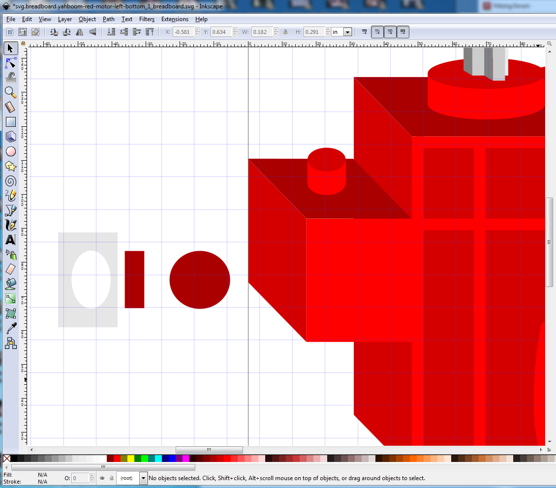
Now we are going to create the illusion that the holes in the tabs are in fact a tube through the tab. To do so make the following (the grey rectangle is only so you can see the white ellipse.) The center rectangle is the back of the case and the right circle is the hole through the tab with fill set to a shade of red (darker than the tab). The left ellipse needs to be adjusted to work correctly when added to the mix.
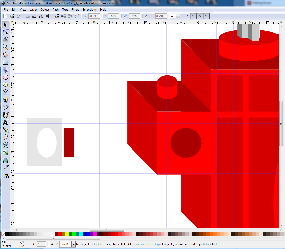
now move the dark red circle to be centered in the tab:
Now move the ellipse over the circle to block part of it out to leave the impression of a tunnel like this:
(you may need to scale the ellipse to get the correct effect)
now move the rectangle over the red circle to create the rear wall of the back of the motor like this:
then do a similar thing on the other side (it won’t be identical to the left this time) to end up with this:
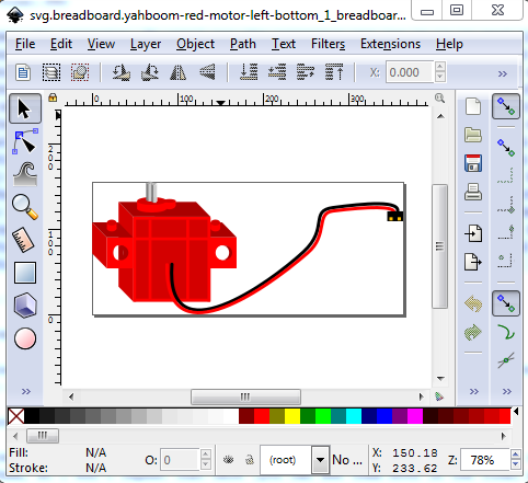
Now comes the connector. Up until now the connector was (as it is in real life) a .1 header. The problem is that the board it needs to connect to has two motor connectors .3in apart on the board. Because you can’t flip vertical in breadboard, that will mean four parts, a top/bottom left motor and a top/bottom right motor (the only difference being the position of the connector) but that is life. As part of this I replaced the two rectangles which were the wire with lines with line-cap:round, then did Path->Object to path to convert them to paths and used the path editing tool (there are Inkscape tutorials on using the path editing tool and I am not very good at it, and so will let you learn from the experts) to adjust the paths to look like the curved and flexible connecting wires. I as noted I reduced the size of the header to fit within .2 in (so two will fit within a .3in space.) This is the bottom left varient. There are 4 parts to this family, bottom left (this one) top left (the only change being the connector moves down til it would connect to a connector .3 in from the connector in the bottom left varient) and top and botton right which do the same thing on the other side with the connector flipping sides. The objective is to be able to connect the motors to their designed interface board (which supports 4 motors.) See also the family howto, to see how the variant field can be used to select these in Inspector in Fritzing here:
and finally the 4 motor variants as they would be deployed:

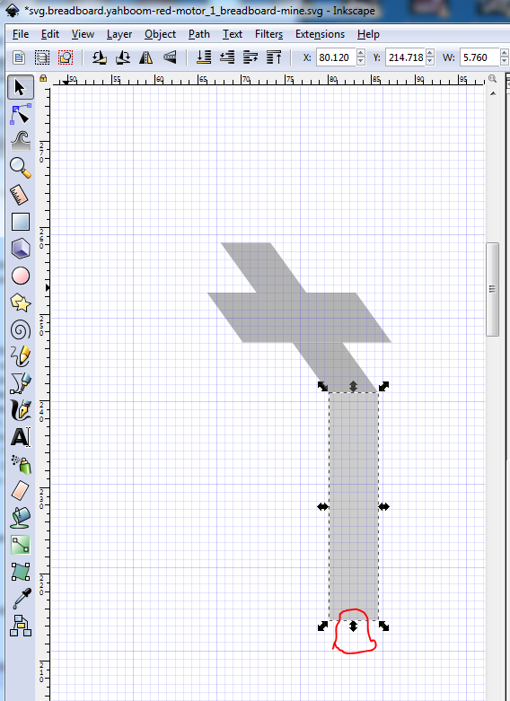
Note: as I write this, there is a bug in Fritzing which, even though the motors are connected (because the connections create rats nest lines in schematic) the routing (circled in red at the bottom) shows as incomplete. You need to connect the pins with wires in order to get the routing complete message at present even though this will work as is.
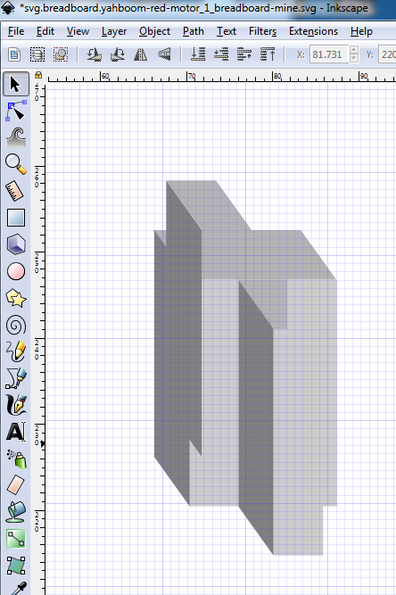
That completes this part’s breadboard. The schematic and pcb are standard, and the earlier howtos detail how to make them, so I won’t repeat that here (you can see them both in the final part here, it will be in the temp parts bin with the .fzz file loaded in to Fritzing):
not-routed.fzz (79.4 KB)
This series continues on to an explaination of the family and variant properties in: