I’ve had trouble trying to find any tutorials on new part creation in terms of the new parts editor, most are based on the old one.
I started with the RGB strip part, renamed it to a .zip and extracted to a folder leaving the .fzp file, and the icon, breadboard, PCB and schematic SVG’s all in one folder.
I made my SVG’s based on those files, Launched Fritzing, right clicked the RGB strip part and selected edit in new parts editor. Then uploaded my SVGs over the top, saved as new part.
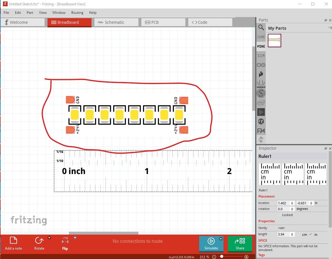
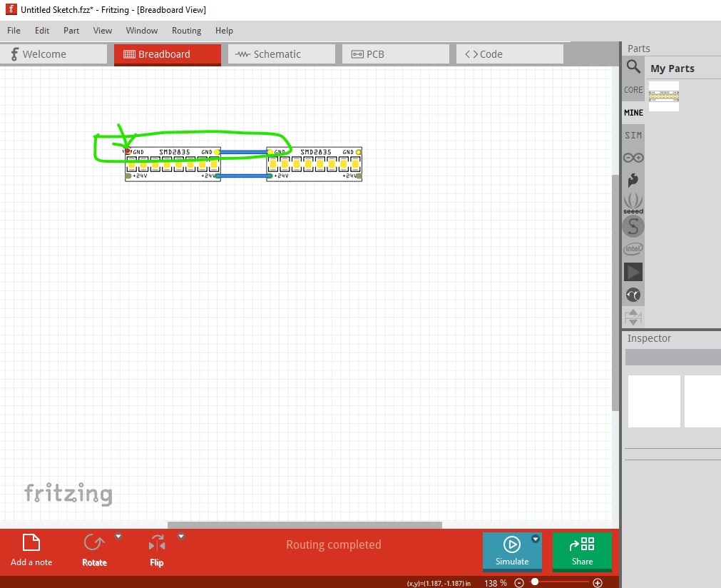
Problem is that when I added to the breadboard, the entire part is red and clicking anywhere would create a wire.
I exported my new part 24V_SMD2835_LED_Strip.fzpz, Renamed to.zip extracted the files and edited the 24V_SMD2835_LED_Strip.fzp file in notepad+++ ensuring UTF-8 Coding remained.
When I was done, I grabbed all 4 files SVG files along with the newly edited 24V_SMD2835_LED_Strip.fzp and zipped them up, then renamed to 24V_SMD2835_LED_Strip.fzpz (Perhaps this is my issue / not the right way to do it?)
If I try opening the 24V_SMD2835_LED_Strip.fzpz from explorer, I get, unable to load part from FILENAME.fzpz
If I try the 24V_SMD2835_LED_Strip.fzp in my original unzipped folder in the same manor,
I get errors saying I need to have the pcb/, breadboard/ prefixes before the images. If I add them back into the .fpz, and create the folders adding in the appropriate SVG’s I get an error saying it couldn’t copy subfile.
Not sure what to try next, any help is greatly appreciated
OK, you have a number of problems here, all of which are correctable. From my point of view google drive is a PITA as I needed to re select the drive for each svg (I initially missed the .fzpz file!) If would be much preferred if you had just uploaded the .fzpz file (which upload will accept, upload is 7th icon from the left in the reply menu.) That said, on to the problems. The main one is that your fzpz file is in the wrong format and thus won’t load as the format is unknown as it doesn’t have a part.part_name.fzp file.
I have added the necessary prefixes for the svg directories and a _1 version number to each file (which is optional but desirable for version control.) Which also reuses the breadboard svg as the icon svg and saves some file space. That done we now run FritzingCheckPart again which still has some complaints to fix up.
The missing terminalIds in breadboard won’t cause a problem (but removing them from the fzp file would be a good practice.)
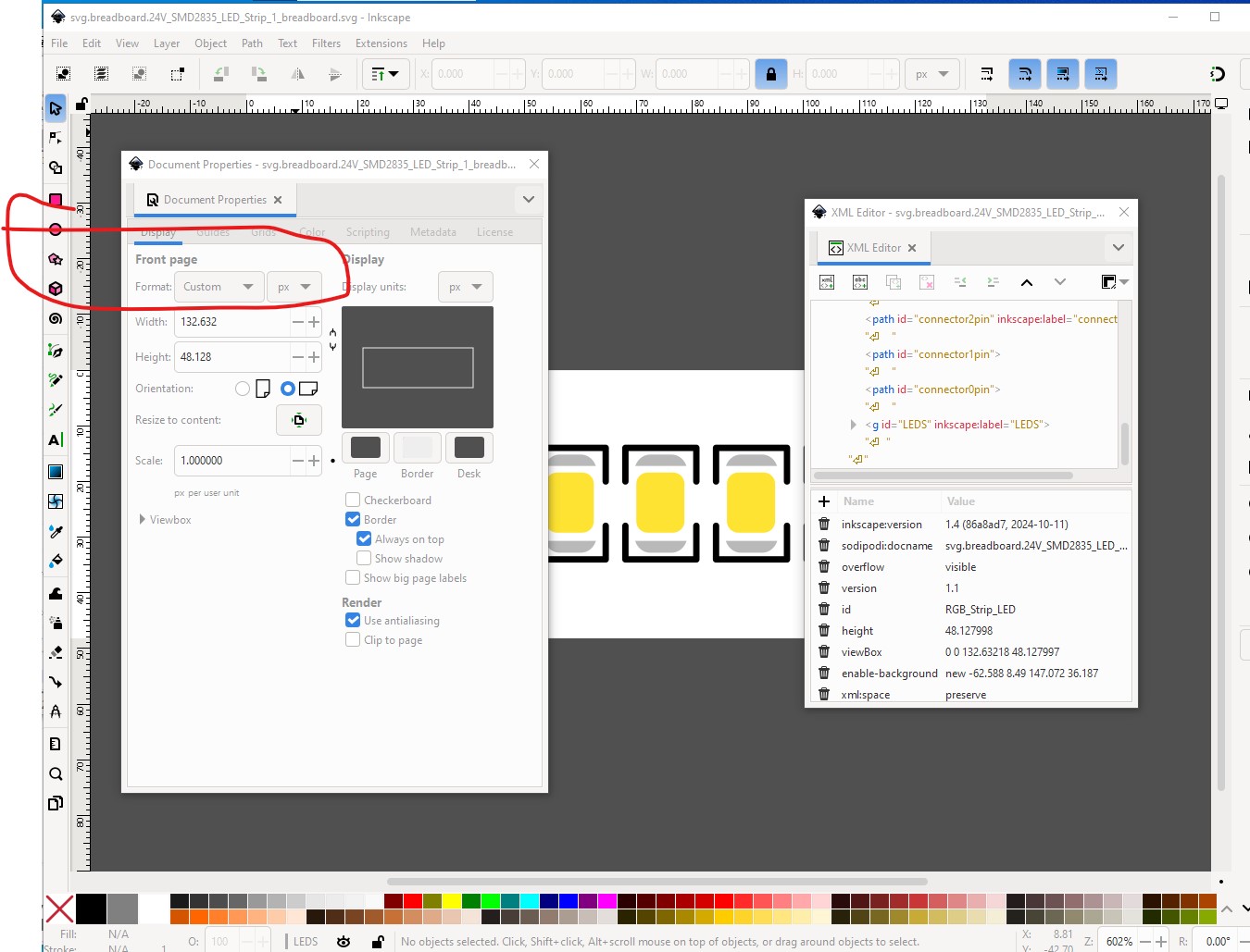
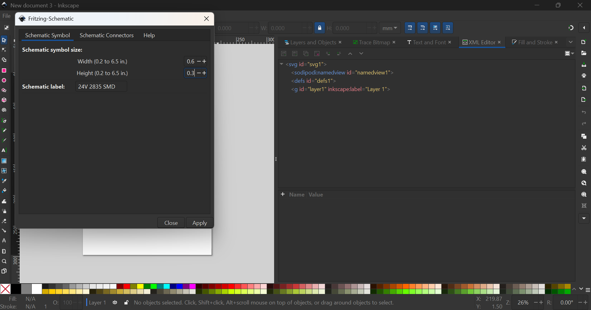
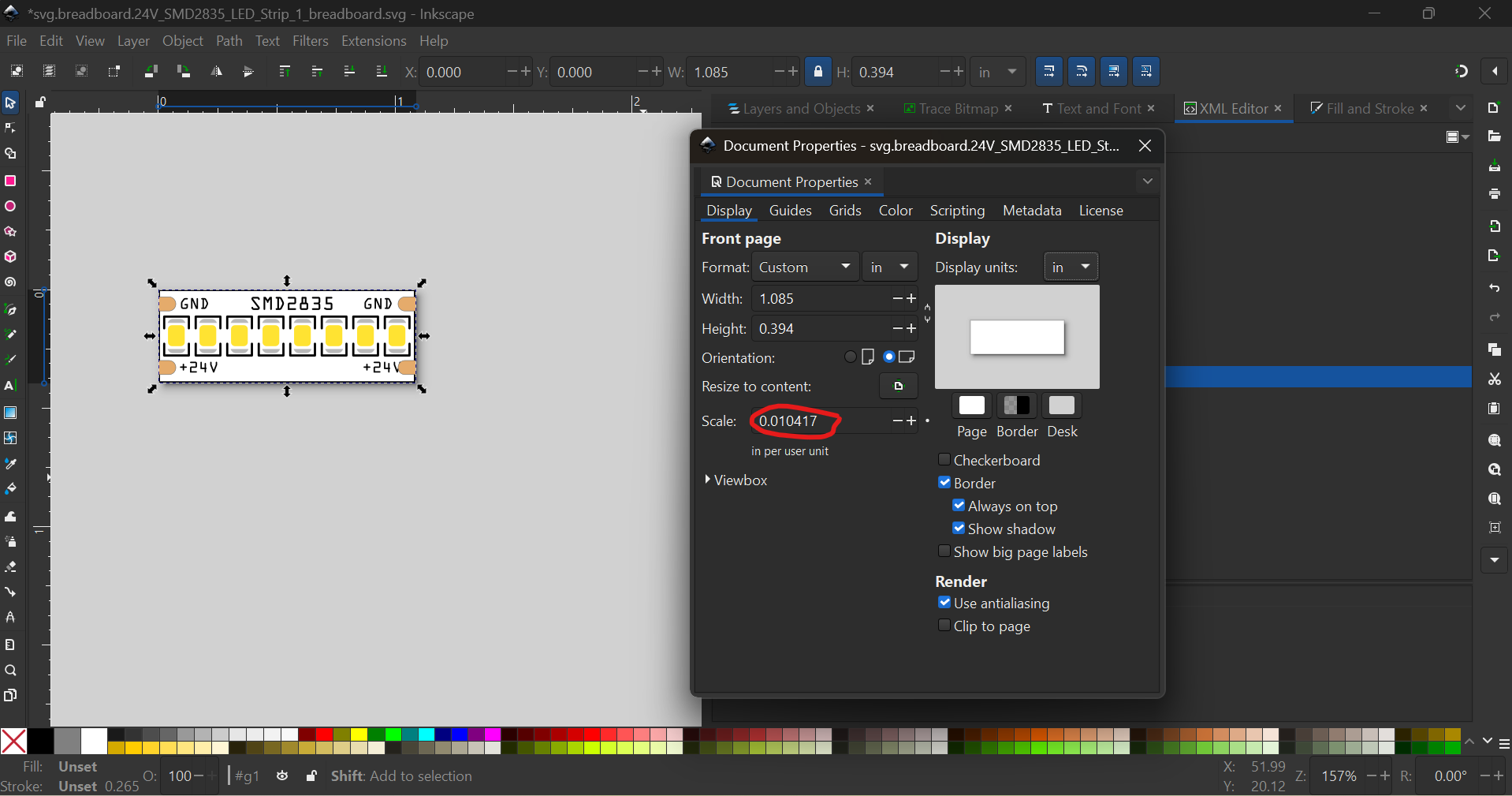
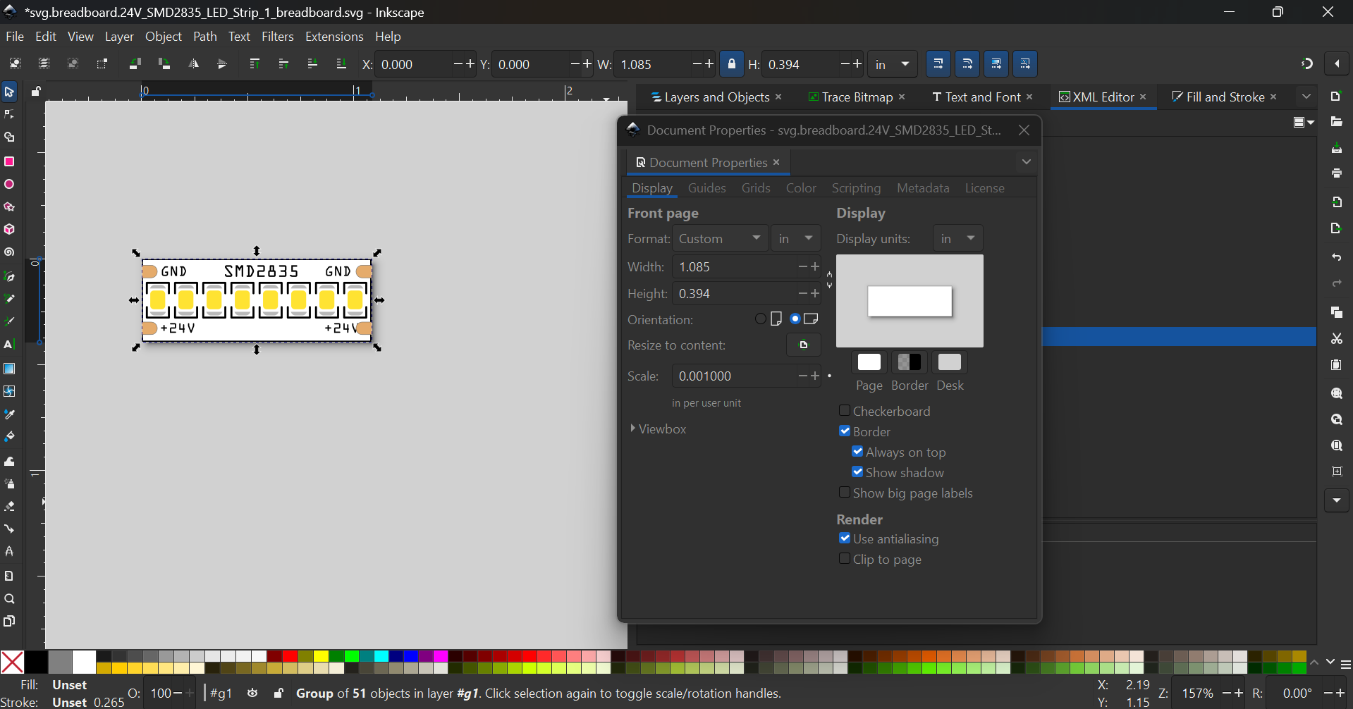
The dimensions in px will likely cause scaling problems if you ware editing the svgs with a current Inkscape version. At present Inkscape is using 96DPI, Friting (given dimensions in px) will guess at either 72DPI or 90DPI (used by older Inkscape versions.) Either guess will scale the svg wrong and make the size of the part incorrect in Fritzing. To fiz that you need to dimension the part in mm or in rather than px like this:
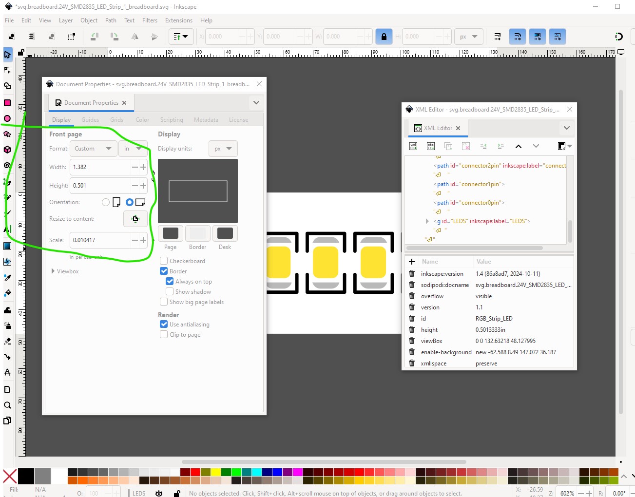
to this which will as noted probably make the scale wrong although if you were using a current version of Inkscape such as 1.4 it will likely be correct as the svg is at 96DPI and will scale correctly when changed to in.
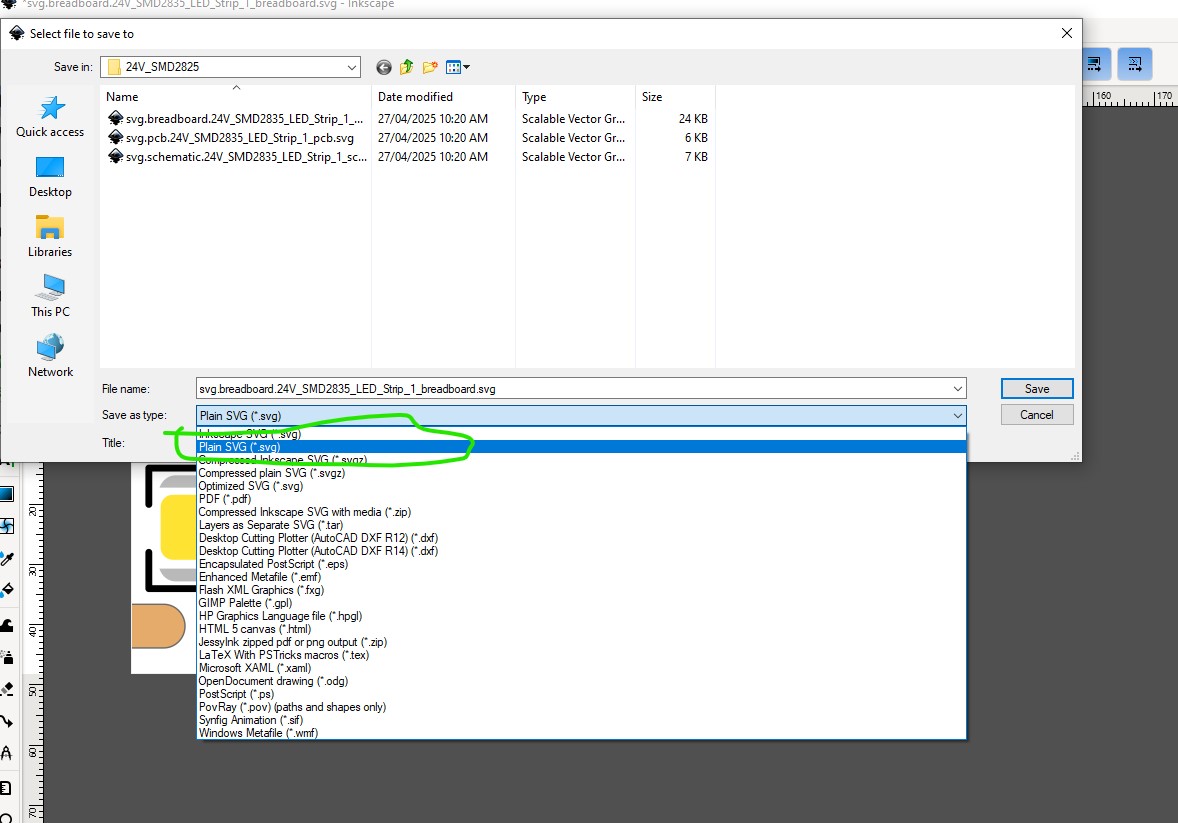
two other things of note, you want to put a rectangle filling the view box to mark the edge of the board of the LED strip (the viewbox won’t render an edge to the board although it will produce an outline of sorts. It is a better practice to specify the edge of the board with a rectangle. The other thing to do is to save the svg as plain svg rather than Inkscape format like this
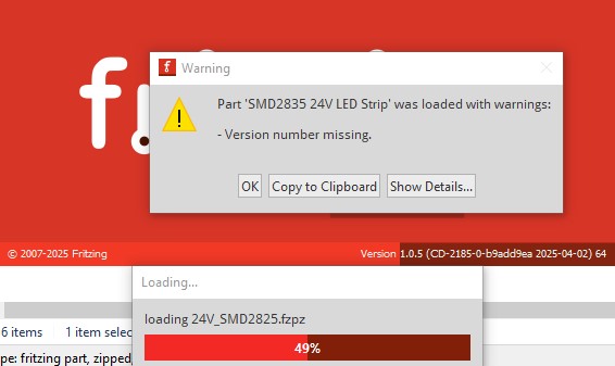
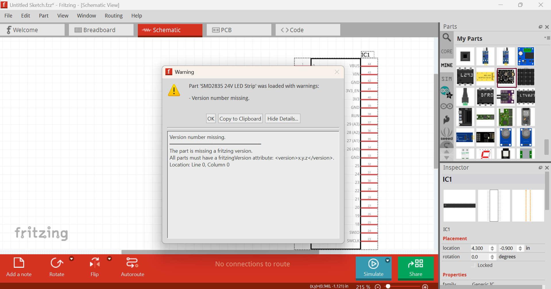
loads mostly correctly in Fritzing (here I am using Fritzing 1.0.5 which has a new error message!)
It appears the version number now wants to have something like 1.2.3 (or in this case probably 1.0.0) for version control (previous Fritzing versions would accept any version number!) Clicking OK to that loads the part (whcih may or may not be the correct size!)
As noted it lacks a board outline and may be the wrong size if the scale isn’t correct (since I don’t know the size of the LED I don’t know how big it should be!) If you have the .fzpz file currently loaded in Fritzing you will need to delete it in the mine parts bin, and then shutdown and restart Fritzing (to actually delete the part, answer yes to keep parts and parts bin changes, no to save the sketch usually) as I didn’t change the moduleId and thus the part will be already loaded if you try and load the new one. If anything isn’t clear feel free to ask!
I don’t think there are any LED strips in core parts and parts from the net run the risk of being dimensioned in px if the person making them didn’t know that was a bad choice. Knowing what to look for is the best defense although not always easy (as making part isn’t easy )
Thank you, I didn’t pick that up as I rarely use the schematic function.
No matter what I tried, I could not get the connection points to work correctly.
I edited the svg files, and the fzp (all in notepad) along with updating the connectors in the parts editor, but it still connects crossed over, it should be ground to ground etc…
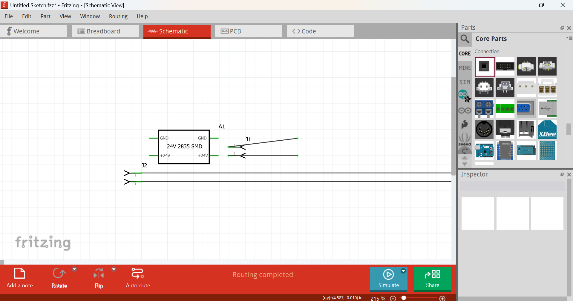
It also looks like the components have switched sides, ie PCB looks fine and in correct order, but the Schematic is a bit…odd.
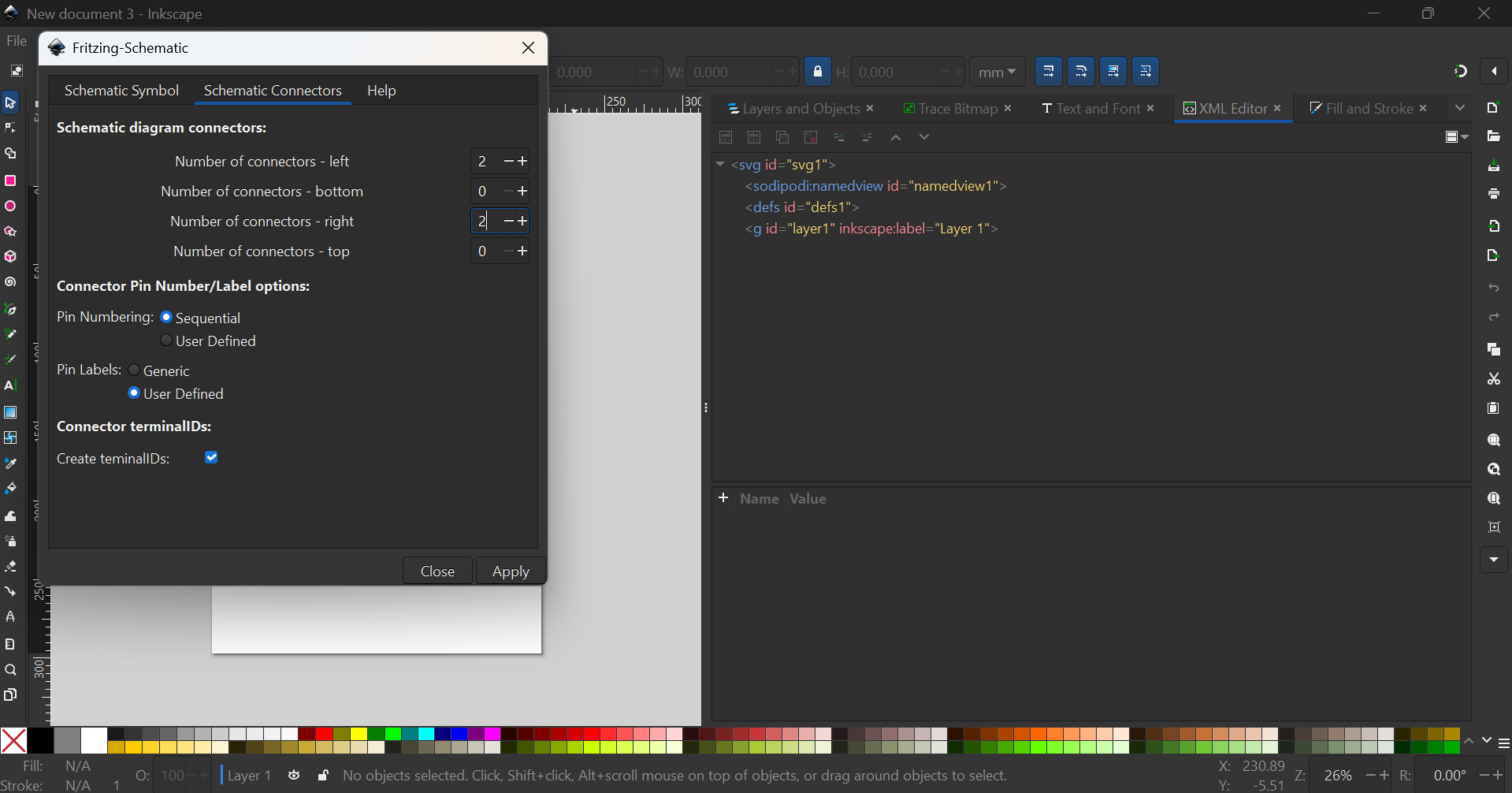
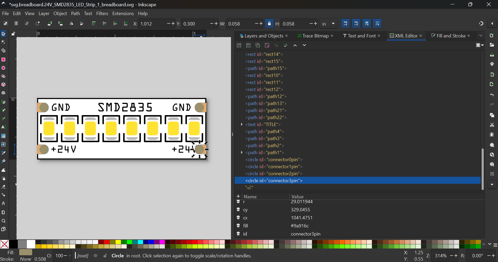
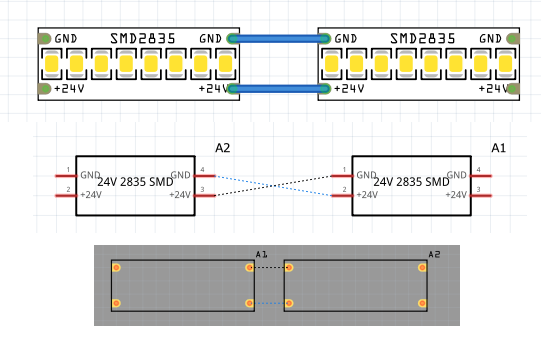
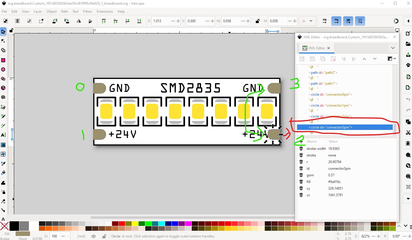
Your breadboard svg is incorrect, connector2 and connector3 need to be reversed as pin numbers follow IC format (0-1 on the left then 2 on the right bottom and 3 on the right top.) The .fzp file is correct but the error in breadboard inverts the pins in schematic. Here I left clicked on connector0 which lights all connections in the net yellow
as expected the correct pins light yellow in breadboard (because the pins are inverted) but connect the other way in schematic which is expecting standard pin numbering.
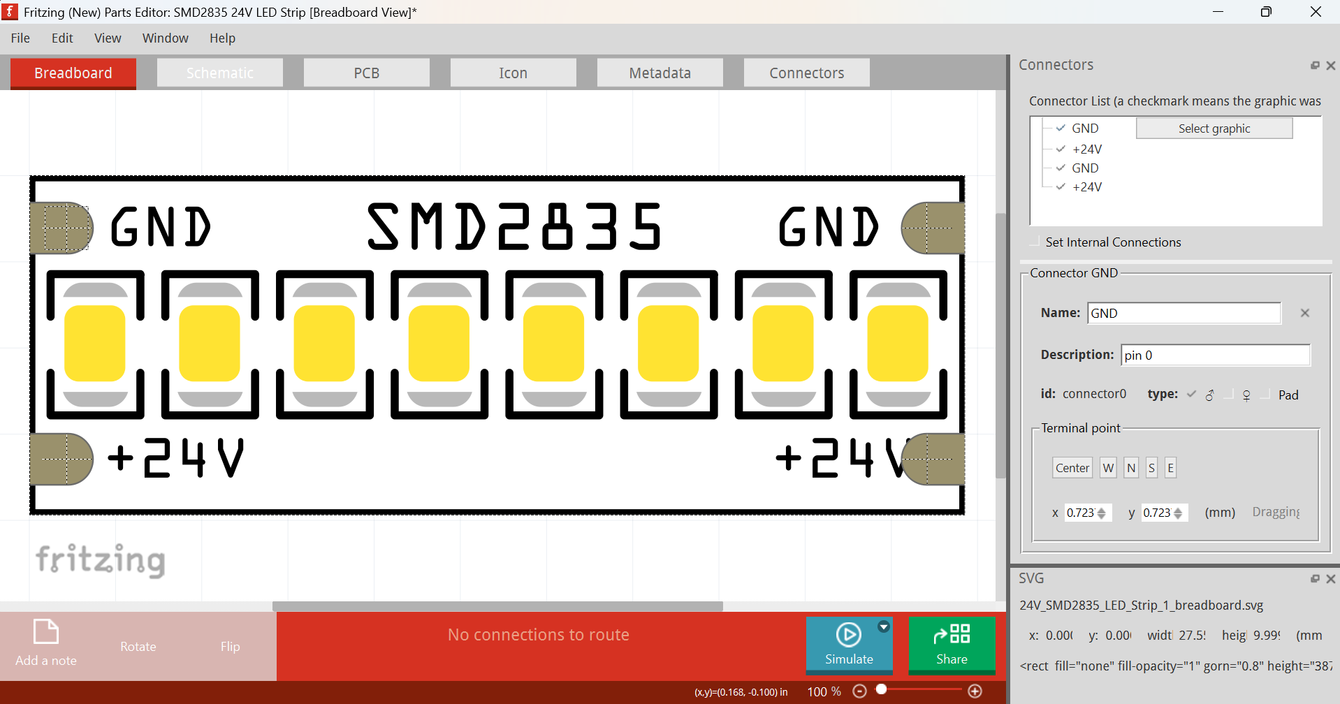
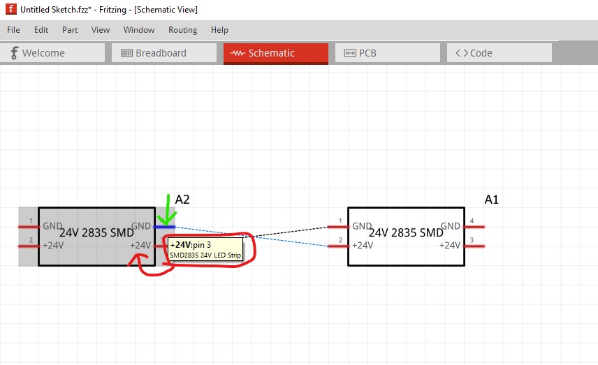
if in schematic I hover over pin 3 (which displays the pin description from the .fzp file) , it calls that +24V (because that is what is defined in the .fzp file) but that should be the bottom pin if the pins were in the correct order.
so the connector numbers in the breadboard svg need to be swapped (connetor2 swapped with connector3) to make schematic correct. You could also change the schematic svg but that would be non standard and thus undesirable. When I left clock on the GND pin in schematic (where the red dot is) we see that really should be +24V and would be correct with the pins on the right swapped.That would then match the definitions in the .fzp file below
I think 80% of my issues was Inkscape not actually updating things as I went, Several times I had to check and the connectors had the original names again.
One odd thing I did notice, was if I ran the E2fRemoveUnusedConnectors.py then zipped things up my breadboard image would be solid red and the connectors broke.
In the end, I updated all the svgs, saved as plain svg,
Ignored the python scripts.
zipped with the .fzp (which also got updated to reflect the swap of connector 2 and 3
Unfortunately still potential problems. A run of your latest part through FritzingCheckPartw.py indicates you didn’t do so and thus there are px in the font sizes. This can cause (usually via parts editor I think) the font size to be set to either 0 (and thus disappear) or huge (and thus be too large.) Inkscape adds the px for CSS compliance, Fritzing objects to it which is why FritzingCheckPart will delete it (along with a number of other things that Fritzing doesn’t support or doesn’t like) and is why the last thing I do after finishing a part and before testing it is run it through FritzingCheckPart to clean it up.
Modified 1: File
‘svg.breadboard.prefix0000_6fbdb41430491ba080df8d6e0bc872e1_11_breadboard.svg.bak’
At line 105
Removed px from font-size leaving 7.2
Modified 1: File
‘svg.breadboard.prefix0000_6fbdb41430491ba080df8d6e0bc872e1_11_breadboard.svg.bak’
At line 153
Removed px from font-size leaving 7.2
Modified 1: File
‘svg.breadboard.prefix0000_6fbdb41430491ba080df8d6e0bc872e1_11_breadboard.svg.bak’
At line 201
Removed px from font-size leaving 7.2
it would be desirable to remove the terminalId from the breadboard connector definitions which causes this error
which in practice won’t hurt anything because Fritzing will ignore the missing terminslId and the pad is correctly aligned as is (it would cause problems if the pad was not symmetrical or if you need a terminalId to move the wire connection to the end of a line which sometimes is needed in breadboard.)
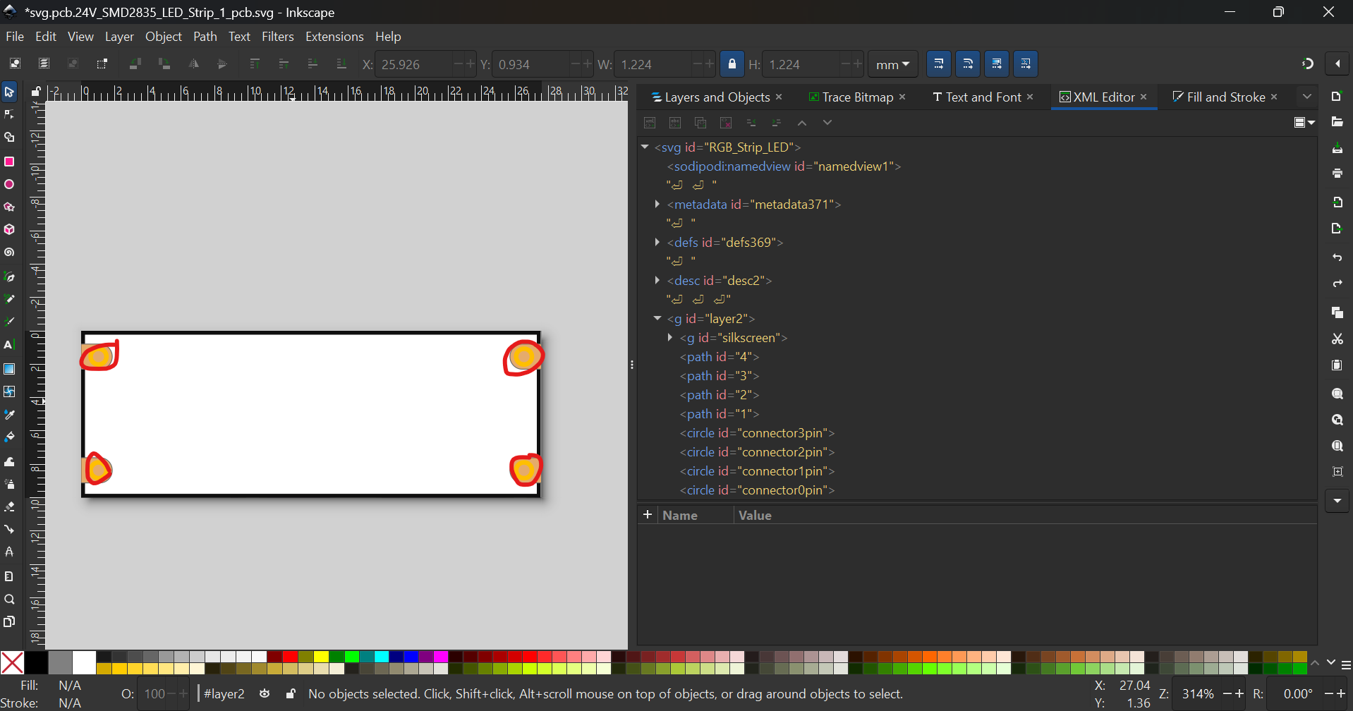
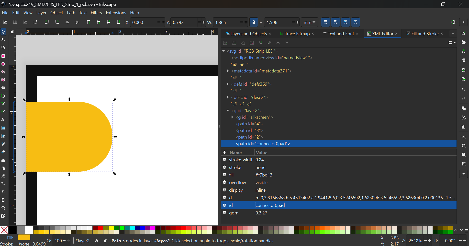
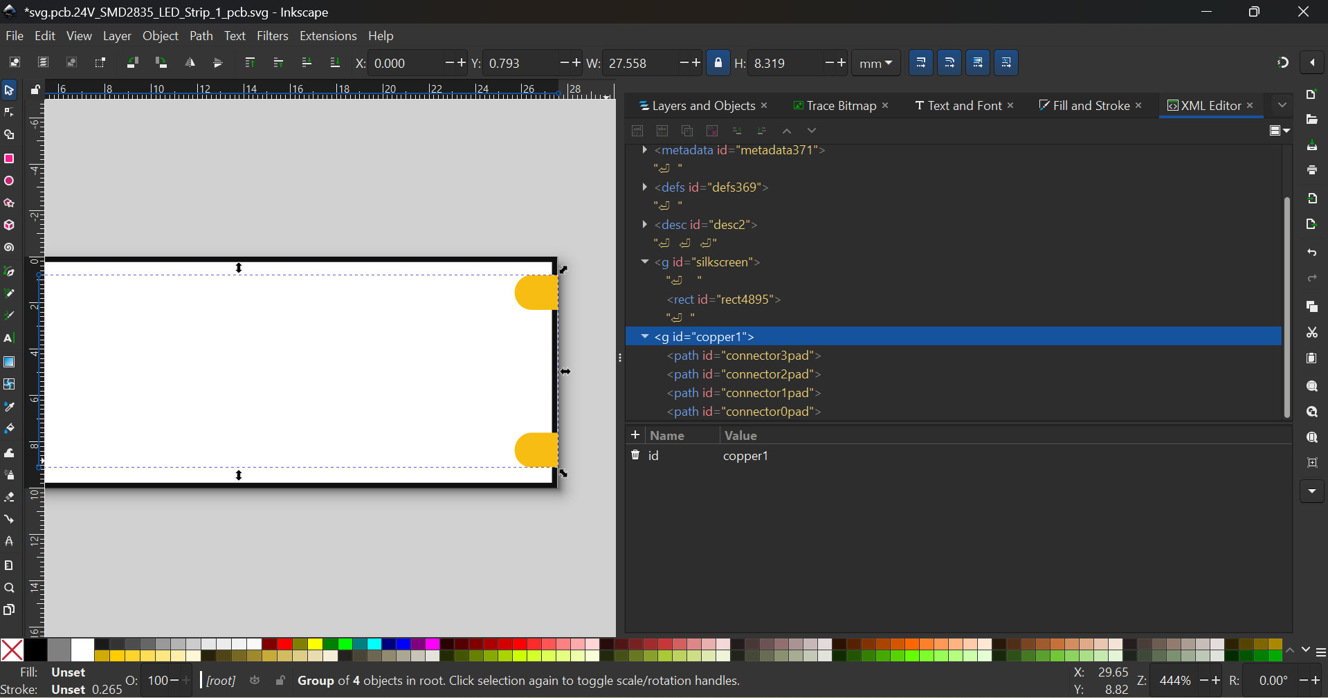
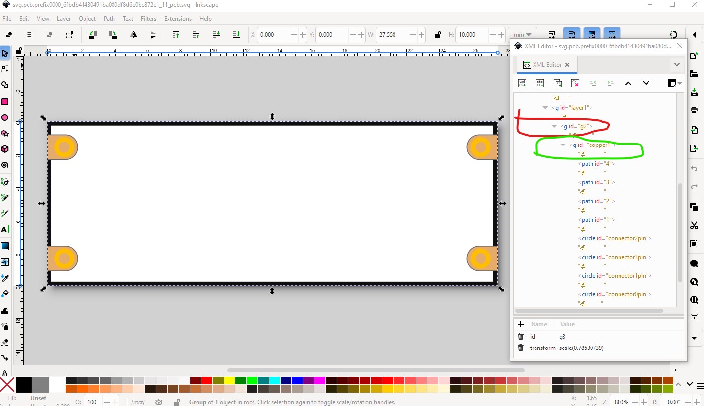
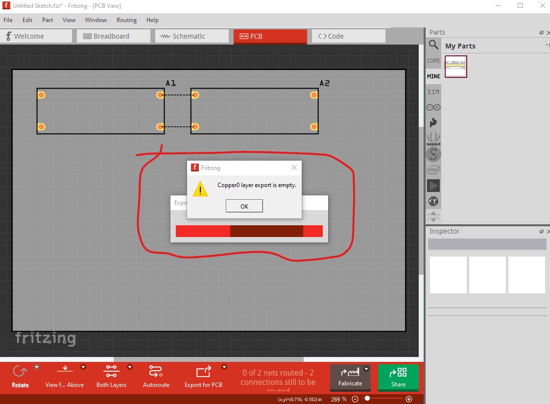
Spoke too soon. When I tried to export as geber to check the hole sizes it tells me copper0 is empty which is incorrect in a through hole part (and means the holes won’t be drilled in pcb.) Here is why:
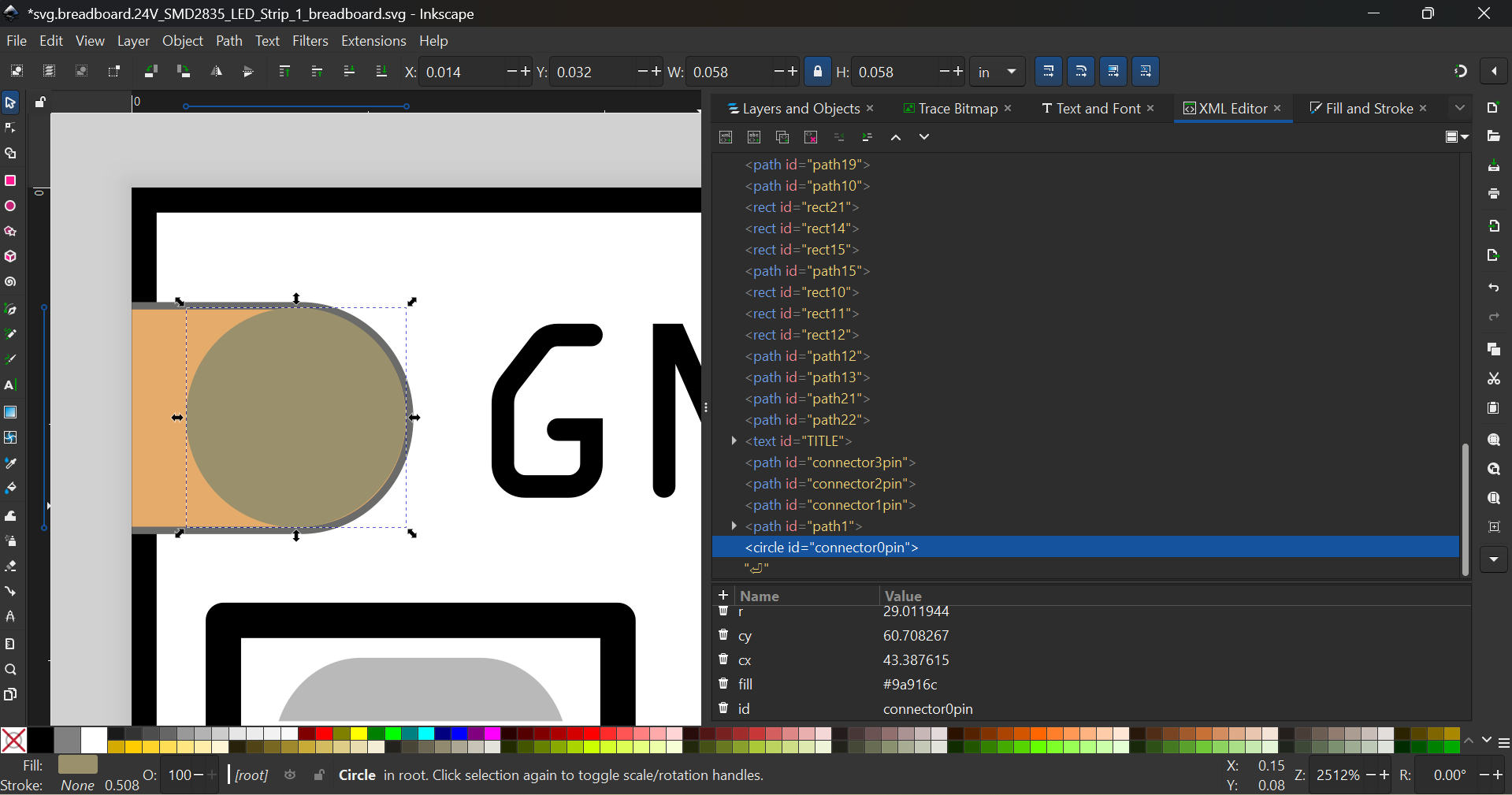
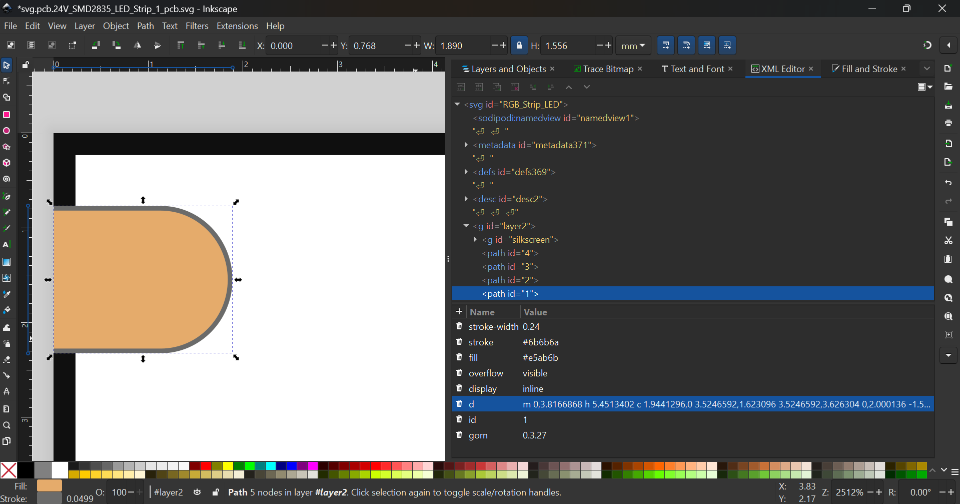
The group circled in red needs to be copper1 with copper0 as a child group. This may be because you didn’t click within the xml editor pane in Inkscape (in which case it doesn’t update the label, happens to me all the time!) Correcting that should fix the problem. Then you need to check the hole size. For Inkscape the hole size is
hole_size = circle_diameter - (2 x stroke-width)
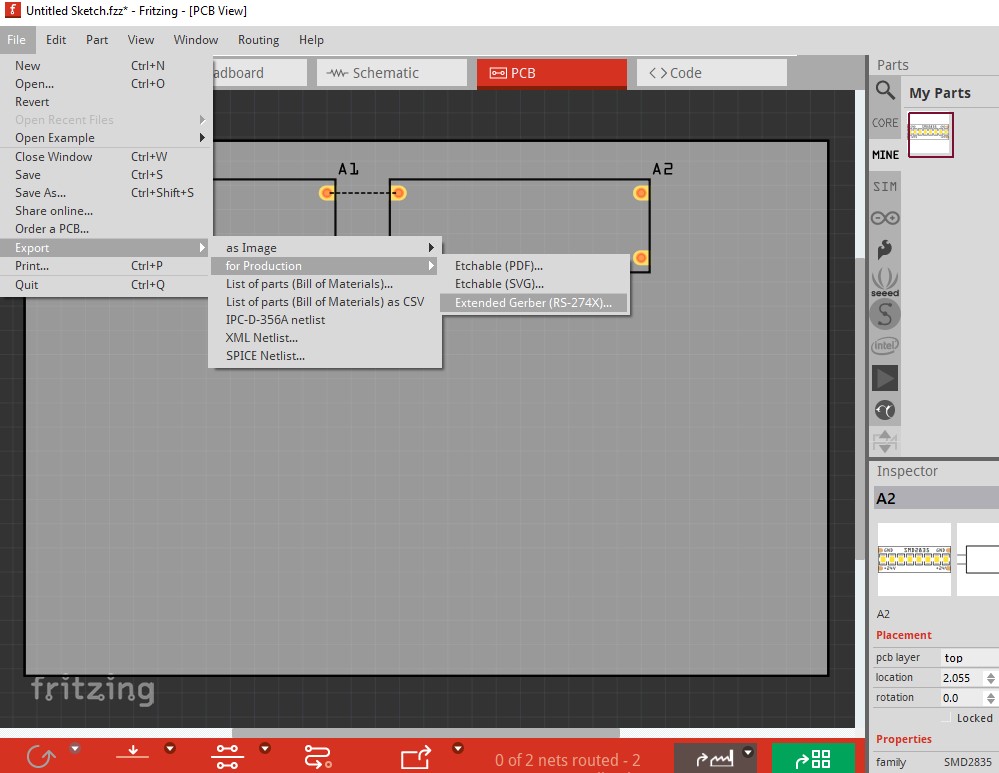
for this you probably want the 0.1in header size which would be 0.038in. To export as gerbers do this
line 257 connector ‘connector2pin’ deleted as unused.
Y:-- Arduino –\Matts Fritzing Parts\setbb-E2fRemoveUnusedConnectors-develop\E2fRemoveUnusedConnectors.py:132: DeprecationWarning: ‘count’ is passed as positional argument
Id = re.sub(r’pin’, ‘’, Id, re.IGNORECASE)
Y:-- Arduino –\Matts Fritzing Parts\setbb-E2fRemoveUnusedConnectors-develop\E2fRemoveUnusedConnectors.py:136: DeprecationWarning: ‘count’ is passed as positional argument
Id = re.sub(r’connector’, Tag, Id, re.IGNORECASE)
line 265 connector ‘connector3pin’ deleted as unused.
line 274 connector ‘connector1pin’ deleted as unused.
Most of the time it removed all correct file and folders names that I had created…,
I have since found, leaving the .SVG alone and simply saving as ‘Plain SVG’ seems to work ok.
I see the tutorial mentioned ‘At times, the text goes wrong when the program removes PX, which was probably also happening, and caused confusion.’
But what I should* have been doing was manually removing ‘px’ from the .fzp files. There is no script for that?
At least this may explain all the back and forth and seemingly weird Inkscape revisions…
IE, user caused.
So am I right in saying, as long as we have the sizing set in the .svg, along with the correct pin , connectors and folder names saving as Plain SVG seems to be ok for me.
Then use a generic IC in Frizting, set to the same amount of pins you have, replace all the items with your Plain format .SVGS
Save as new part / export to get it all in one .fzpz file.
Done?
I think my other issue was that I was basing it on a part that already had a .fzpz, whereas essentially editing a generic IC in Fritzing creates the .fpzp for you on save / export.
Hope that makes sense, I could upload my new part that is 99.9% of the way there, but it should be its own thread. The only issue is the text size / font replacement. I would have thought removing the .px in the .fpz would fix it, but since the .fpz doesn’t exist until after we edit an IC in Fritzing I’m not so sure.
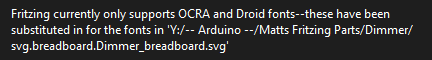
I did try changing the font in Inkscape the those provided with the templates and fonts / Droid Sans and OCRA, but still got the
I’m sure I will find the solution above where you mentioned things about the font size,
But there we go, hope that makes sense. Once I get it down I’ll document a dummies guide
E2fRemoveUnusedConnectors.py is not intended for general use. It is specifically to modify svgs created by Eagle2Fritzing (which have extra connectors) and needs all the connectors to be at the bottom of the svg and with the connector intended to be connector0 labeled as connector0pin+ specifically because the + is not created by Eagle2Fritzing. It is not intended for general use setbb.py and setsch.py are better for that use although they both need the same general format (all the pins in order at the bottom of the svg with connector0 labeled connector0pin (no +!)
FritzingCheckPart.py is the correct script to use to clean up parts and remove the pxs (and other things Fritzing objects to.)
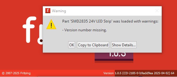
In addition on Fritzing 1.0.5 your part currently gets this error
which appears to be this
Part ‘SMD2835 24V LED Strip’ was loaded with warnings:
Version number missing.
Version number missing.
─────────────────────────
The part is missing a fritzing version.
All parts must have a fritzingVersion attribute: x.y.z.
Location: Line 0, Column 0
and I am not at present sure why (it only happens in 1.0.5, 1.0.4 loads normally so it may be a bug.) I will figure out what it is objecting to and post.
OK, there looks to be a bug in 1.0.5 (which I will report) it appears to be flagging the version field when it really means there is no fritzing version present. In the .fzp file this