The board just got a bit bigger because the new display is larger, and I think there is a problem with the encoders. They are a breakout board and I just realized they mount at 90 degrees which may not be what you want. From the breadboard view of the encoder

It is intended to connect via the right angle header which isn’t what you want here. You want the bare encoder to solder on to the board I expect. There is an alternative part here, but I don’t know if it will do what you want (I think it is mechanical rather than optical as the RSdelivery one apparently is.) The RSdelivery one could have the right angle header unsoldered and the part modified to mount it flat with the shaft going vertical (which is I think what you want.) A better bet may be unsoldering the encoder part and making a part for that (but then we would need to figure out the pin spacing which shouldn’t be that hard with calipers. There is one that I think is similar (but perhaps not identical) that has a Fritzing part here:
Unfortunately that post doesn’t give the Alps part number for the encoder I think it is probably this one.
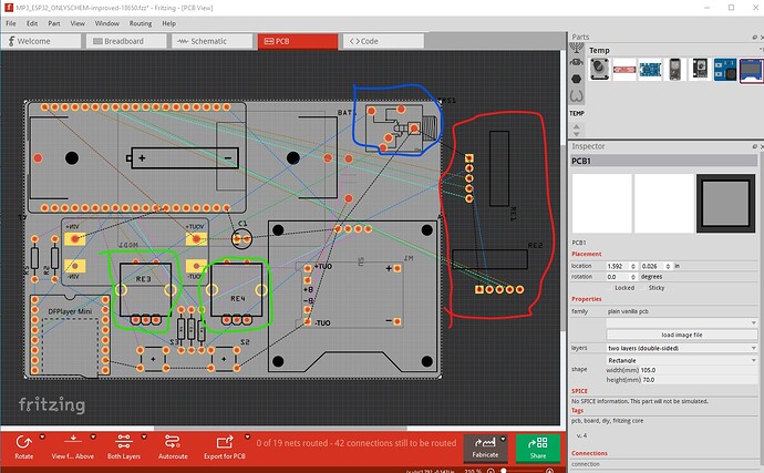
I also don’t know what the AZdelivery one does exactly other than it has a NO pushbutton switch as this one does. Neither of them say how many pulses per revolution. If you already have the AZdelivery ones you could unsolder the encoder from the board and I can (given the pin spacing make a part for it which may be the easiest solution. Here is the new board with the 1.54in OLED installed and pcb enlarged a bit, the alps encoders installed (but not in schematic yet) and placed where I think is sensible. You can move them around to suit your needs as long as you watch the overlaps. The MP3 player moved to the edge of the board because you will need a slot in the case to insert the SD card in to so you need to take that in to account too. Here is the sketch
MP3_ESP32_ONLYSCHEM-improved-18650.fzz (114.2 KB)
and an image of what pcb looks like.
Note the size of the pcb (in the lower right Inspector window) has increased a bit to allow for the size of the new display. The new encoders are circled in green, the jack circled in blue is only for the wires to the real jack on the case, the old encoders are off board and circled in red. As noted you can move things around as you like to get the layout you need as long as parts don’t overlay.
Peter
