Hi, everyone,
I’m new to this forum because I want to learn more about circuits and circuit diagrams.
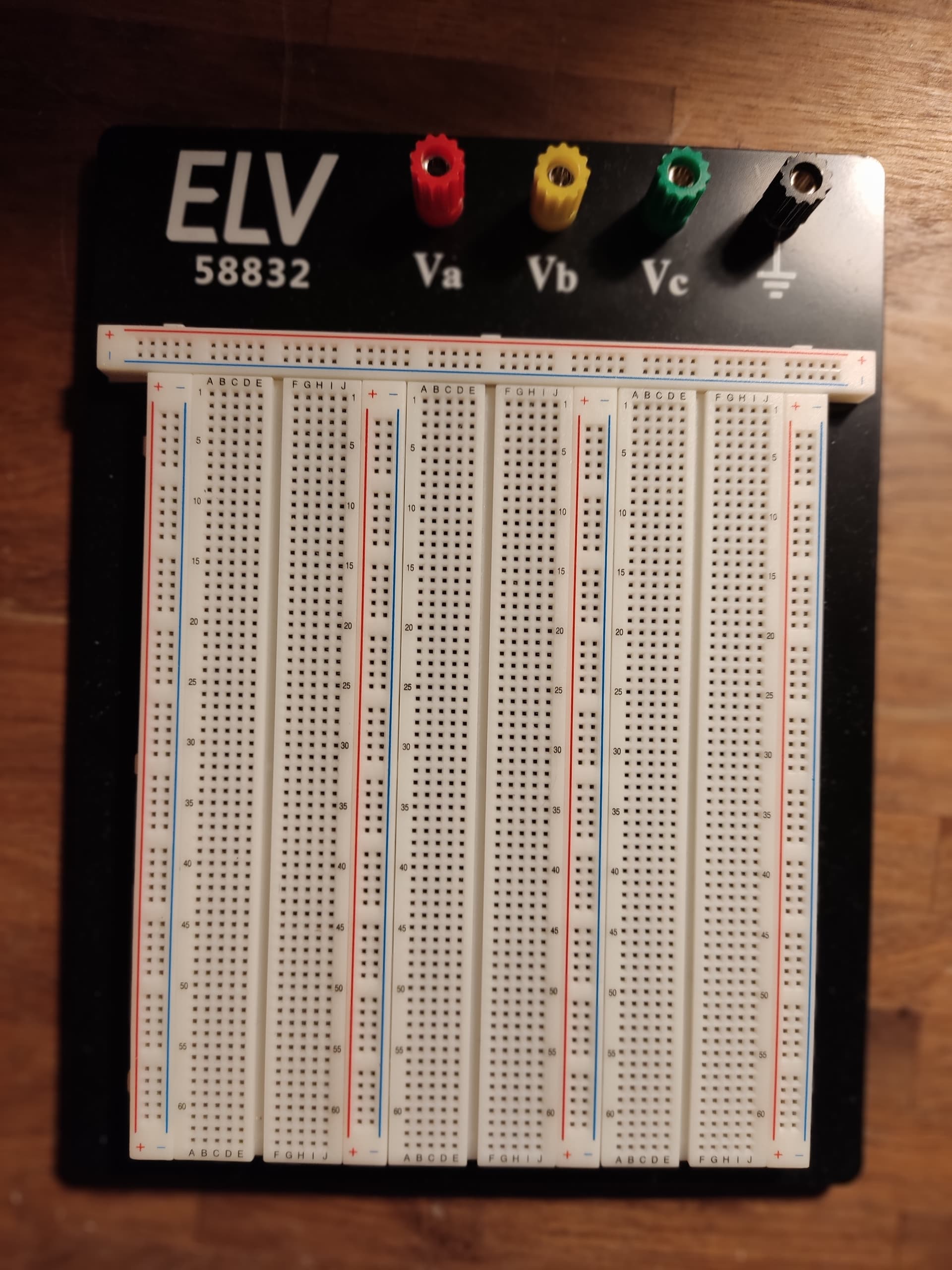
At home I use the ELV 58832 breadboard. It’s perfect because you can use almost all MCUs, including an ESP32.
from the electrical leads, there should be no problem creating this breadboard.
who out there could create this part for fritzing?
Many thanks in advance !
hello peter,
NO THEY DON’T !
why:
u cannot plug an esp32 on this bread-board having at least one column free per side.
u can plug it in one of the
;;;;; ;;;;; - sectors, but then u only have one free column, but only on one side:
|;;;; ;;;|; (| = pinrow esp32).
because of having TWO +/- coupled (! why ever) lines you cannot plug it in that sector.
;;;;; ;;;;; -+ -+ ;;;;; ;;;;; → there is no place for an esp32 …
MY BEARDBOARD only have ONE +/- line, and there you can plug in the esp32 bloody well :
;;;;; ;;;;; -+ ;;;;; ;;;;;
;;;;; ;;;|; -+ ;;|;; ;;;;; … “|” is the pin row of esp32
=> u have a minimum of TWO FREE columns each side ! that’s perfect, isn’t it ?
thanks a lot and soooo fast - wow !
one more overlapped breadboard and a additional horizontal powerline and it would great - the worldwide best breadboard for all mcu (esp32 has the max width of them) and the longest has bloody much place on this board …
SUPER !
thanks a lot, peter.is it difficult to add a horizontal power rail ?
of course it is not as important as the placement of the esp32. but it would be nice to have it. (fulfilled wishes get kids, mostly like the pigs )
here are some skills:
2390 contacts (done, thank you)
3 connection panels with a total of 500 power distribution connections and (done, thank you)
5 wiring panels (horizontal missing) 4 measuring device sockets Sturdy metal support plate with non-slip rubber feetIncluding
Dimensions (W x H x D): Plug-in board: 165 x 175 x 8.5 mm, support plate: 230 x 175 x 15 mm
you’re so great, peter !
i love vancouver et j’aime parler francaise. Dans ce sens … merci beaucoup
hi peter,
wow, that’s what I call a big surprise. Thanks so much !
how do you get that so fast?
what do you eat in the morning?
… or is it the climate in vancouver?
stay healthy !
thanks again; now i feel good with fritzing
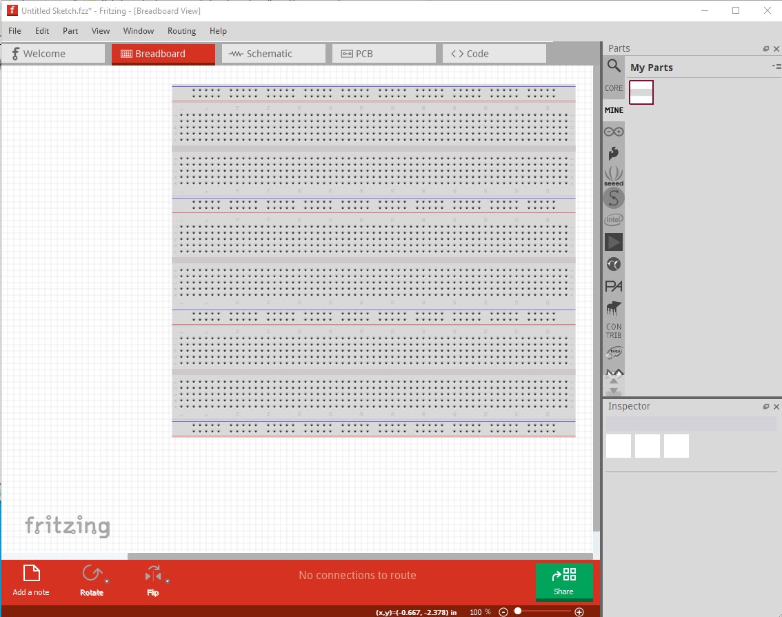
If you are familiar with breadboards and making parts it is fairly easy. I just copied all 4 breadboards (2 full, one no power rails and the power rails) in to a single svg, then used vi and regular expressions to modify the pin names and group names to be unique in both the svg and fzp file.
hello peter,
however, there is one small flaw:
the minus column of the left inner plus-minus bar is one slot too narrow. the right inner plus-minus bar is fine.
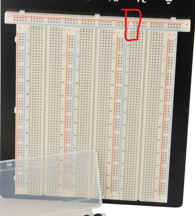
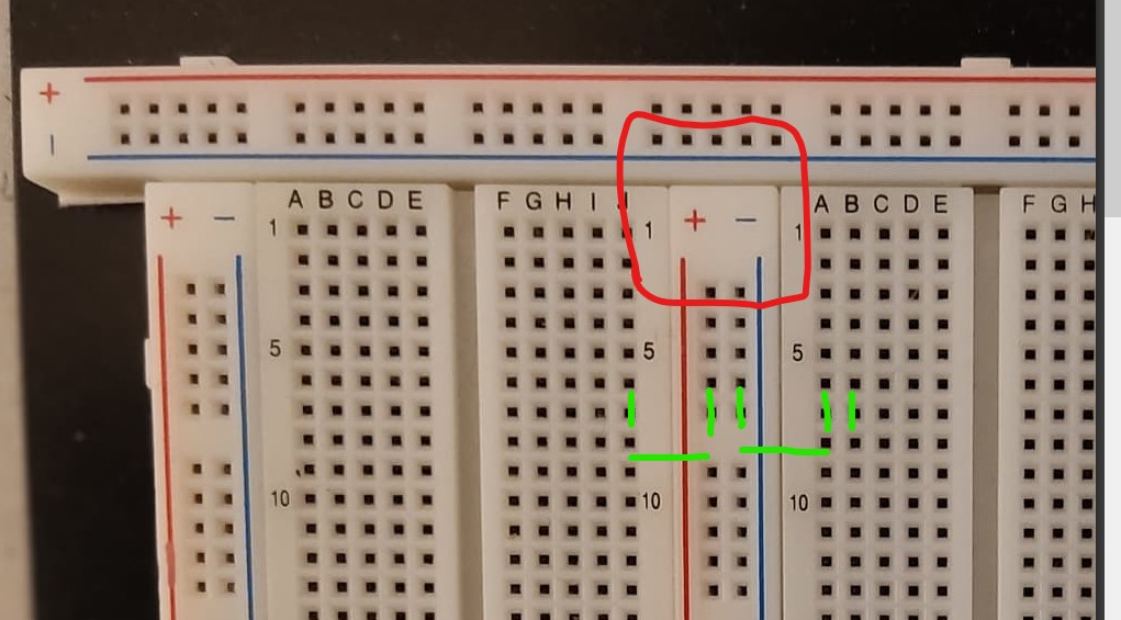
OK, I just replaced the part above with a corrected(?) version. However that appears to misalign the top power strip by one position according to the jpeg image of the board (which isn’t the best!) The lines circled in red now appear to be misaligned:
but perhaps aren’t in real life? Or is the top power strip odd in some way (has an extra space somewhere?) In which case I need to know where the additional space is to modify the power bar (it is currently identical to the standard breadboard power strips.)
… it seams that the left power-line (+/-) is a little bit bigger (the blue one) … and maybe a little bigger than the right power-line of the right side of the board ?
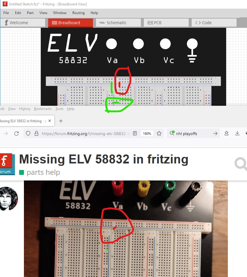
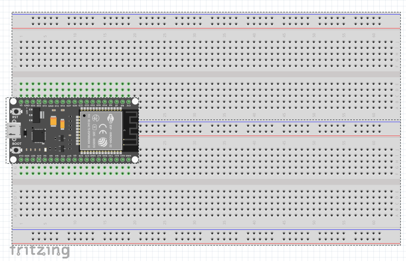
The top image is the part in Fritzing the bottom your photo. The top power lines (marked in red) look to be slightly misaligned starting at the middle breadboard. It won’t make much practical difference as long as all the breadboards are correct in the horizontal direction (the green circled place between the first and second breadboards) as the power lines are all common and if they are a bit misaligned it won’t hurt anything. It is just puzzling why it is misaligned since it seems to start out correct, and the top power strip doesn’t seem to have any odd gaps. It is possible that there is an extra space on the top power strip where the red circle is in the photo. If so it is easy enough to move the power strip pins 0.1in to the left to make it correct, I just don’t know what is correct!
… then yours will probably be right, because :
on all my breadboards - i have two - the horizontal power strip curves slightly upwards on both breadboards, i.e. the highest point is the vertical center line. all elements are screwed on from below. and as it looks, additionally fixed with double-sided adhesive tape. I think that when assembling, the side tabs/grooves don’t match properly, or that the horizontal power bar is pushed up slightly when screwing it together…
the difference in height can be clearly felt when you run your fingers over it… i’m guessing it’s just under 0.5mm…
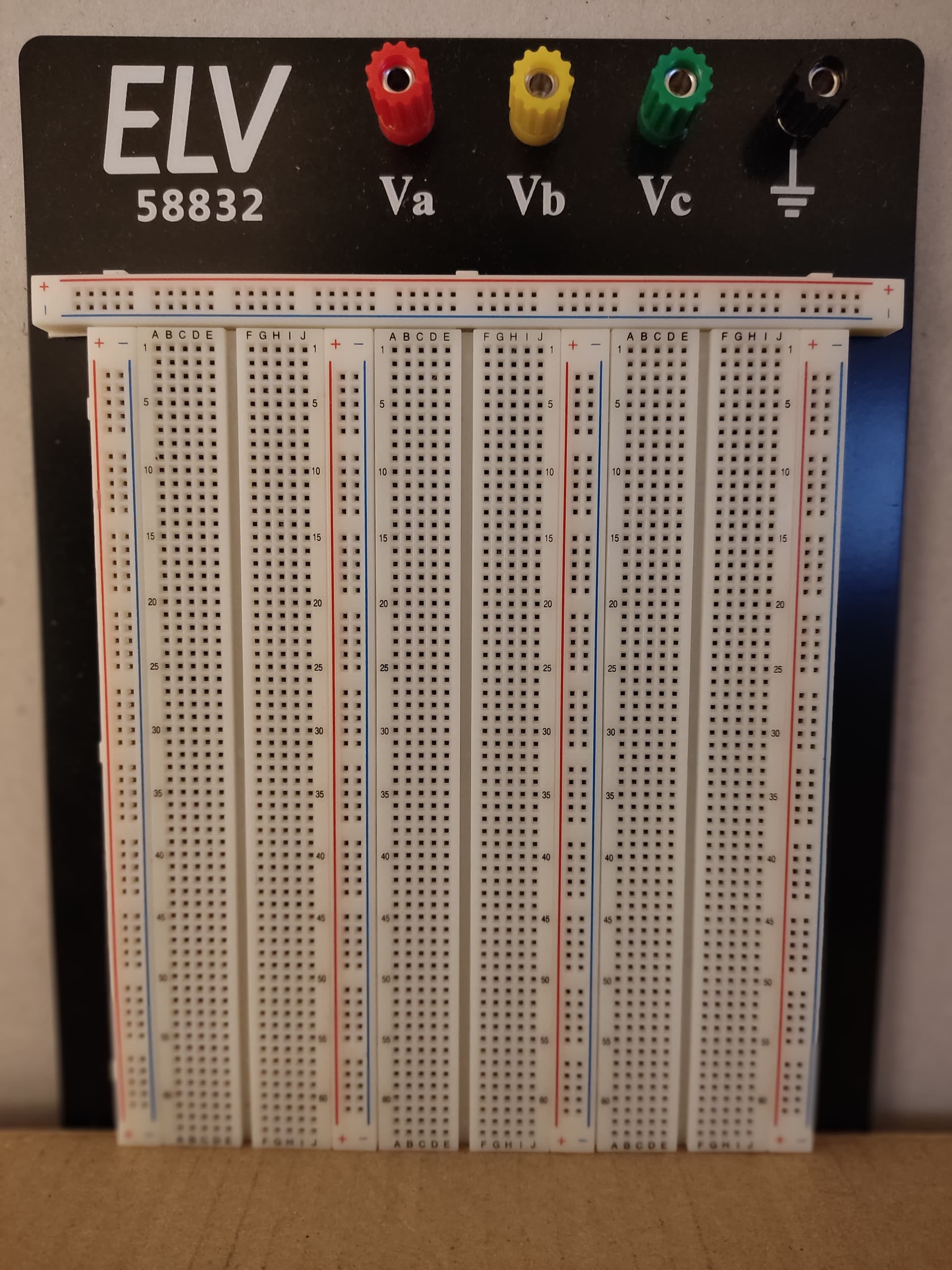
i think the photo you have was taken when the board was vertical; I had it on my table…
I’ll put the breadboard upright and take another photo…
As long as the breadboard spacing is correct horizontally I expect all should be well. As noted even if the top power strip is misaligned a bit it won’t affect function.
Yes it looks like the power strips may be a bit misaligned. As long as the spacing on the breadboards is OK (and it should be in the Fritzing part as they are all on 0.1in boundaries) it should work fine.
in the photo it looks like the middle power strip is offset by about 0.05in from the top power strip. As long as there is 0.3in between the green horizontal lines in the image all should be well as the breadboards should be correctly aligned (at least in Fritzing) and should be close enough to connect with a small bend in real life. It is hard getting parts right when you don’t have the part in front of you to measure with calipers .

 )
)