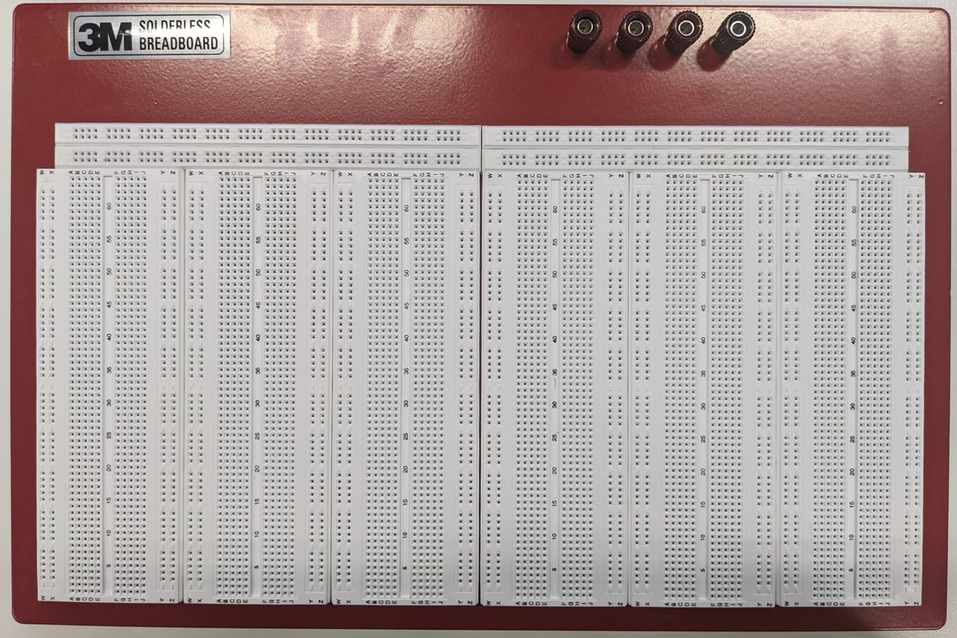
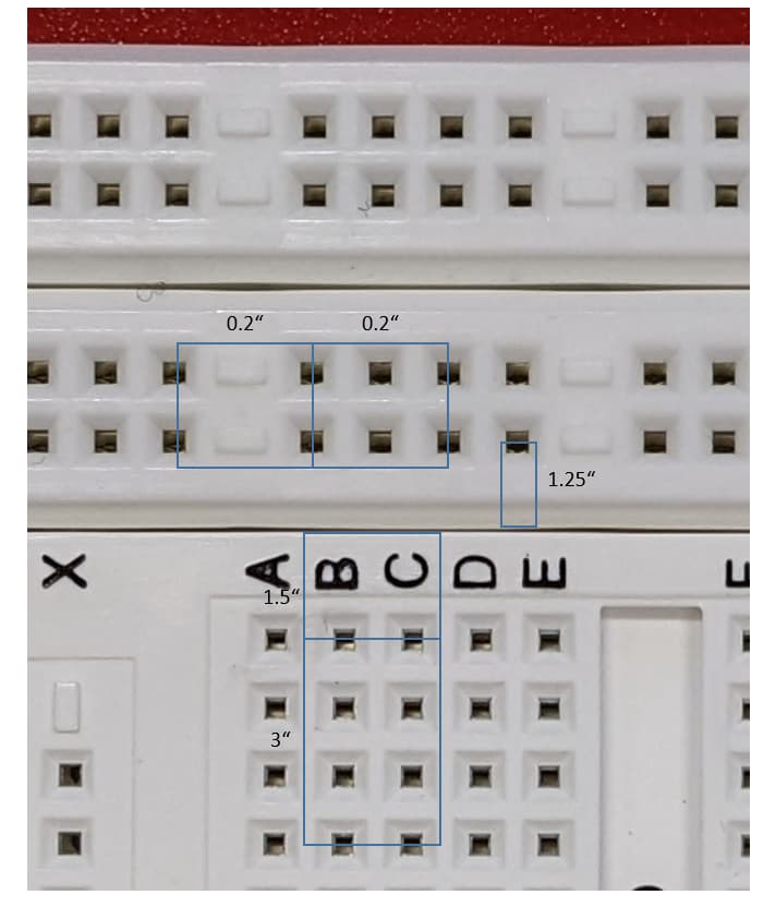
The tie points in the red boxes are alway connected.
I was wondering if someone already uses this kind of breadboard and distribution strip and could share the firtzing part (library) for it.
I am not familiar with building parts and breadboards so far. If someone could provide me a link for
a tutorial “How to build a fritzing breadboard”…I would try it
There is a tutorial for making parts, but it doesn’t currently include breadboards (which are a special case for a variety of reasons) because not many people need to do it.
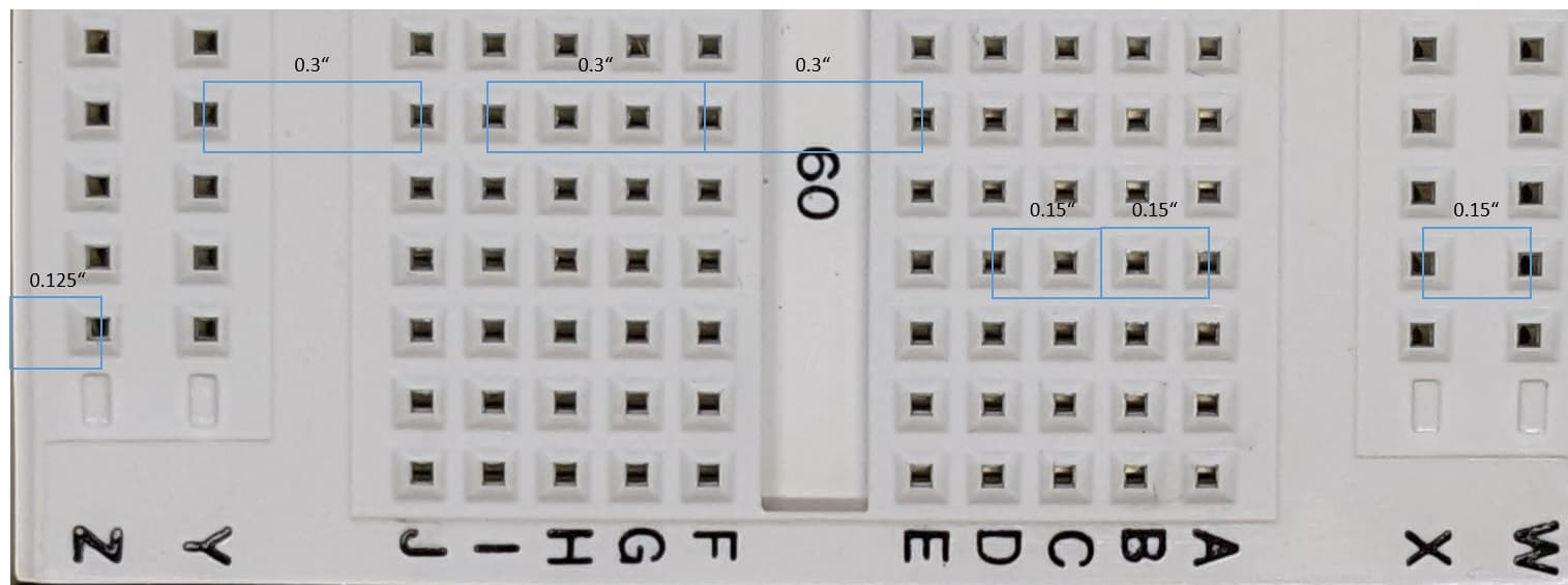
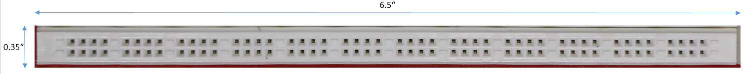
The breadboard looks to be a standard full+ breadboard but with somewhat different power rails (the two isolated 5 pin sections in the middle). The distribution strip is pretty standard (I made a shorter one for someone.) I’ll have a poke at making the two necessary parts as I have built breadboards before and post them in a while.
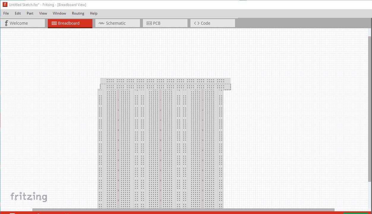
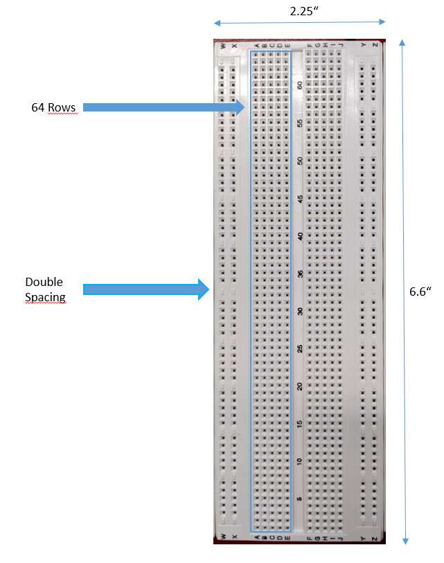
Comparing to the previous image, it appears that the main breadboards are not positioned “flush” to each other. There is an additional .1 in separation between the adjacent (vertical in the picture) bus lines. Also, it appears that the distribution strip is not aligned on the same .1 in grid as the breadboard. It looks offset by 0.05 in. I would be tempted to implement as 2 parts. A distribution strip, and a breadboard. Then use 2 strips and 3 breadboards as a set.
It also appears from the original picture, that the bus lines on the breadboard have a 0.2 in gap in the middle, instead of 0.1 in
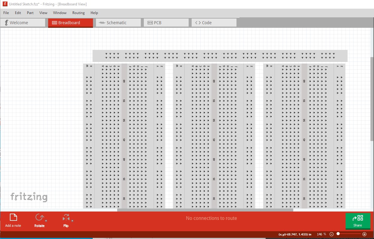
Good catch! That appears to be it. There is an additional .1in spacing between the breadboards that I didn’t catch. The power strip is already a separate part, and it looks like it needs a little width adjustment too. I saw the 0.05in offset between breadboard and power dist rail, but there isn’t a lot I can do about it, as the pins on the dist panel are on 0.1in boundaries and thus will snap to the grip to match the breadboard (and previous attempts tell me I won’t be able to offset that in the svg in any way I know!) so we have to live with a little maladjustment. Here is a closer arrangement which indicates I need to to some adjustment to the base breadboard widths to get closer to real life!
It also looks like the breadboards themselves are (even more) special. There should be an extra 0.1 gap between blocks 5 and 6 of the rails.
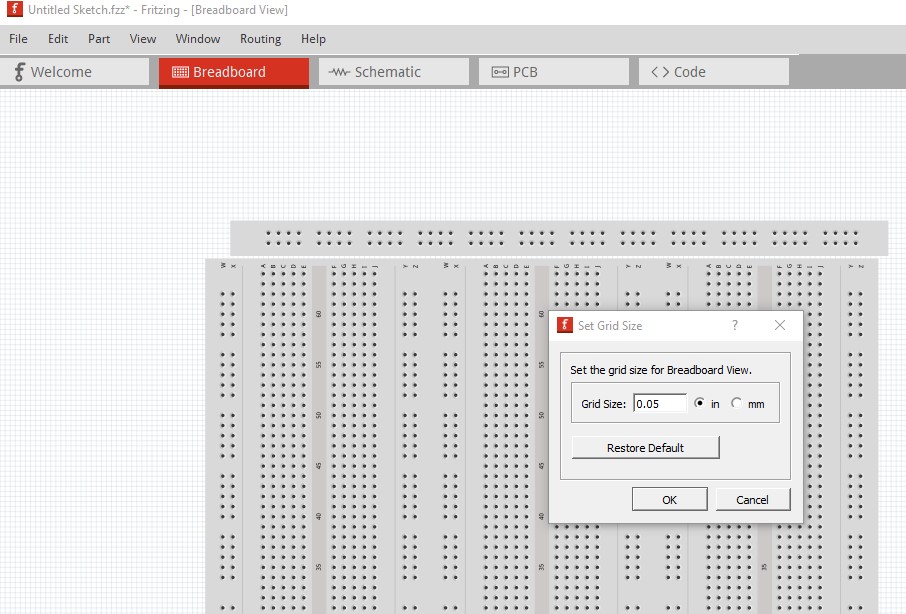
You can get the 0.05 offset when positioning the distribution stripe by setting the grid spacing to 0.05, position, then lock, then change the spacing back to 0.1. But no, with the current code, there is no way to do that in the svg.
OK I think this is as close as we are going to come. I just replaced the two parts with updated ones that I think fix all the issues (and changed the sizes to match your drawings.) The power connector still looks a little wrong but it should work.
via View->Set grid size, then moved the power distribution strip to 0.05in past the pins on the breadboard. As you see it doesn’t match the photo but should work the same.