In another link, I posted info on the sdCard Adapter I use (senmod sdhc adapter). I’ve used them enough now that I decided to make a ‘Part’ for it.
Info:
• I like big pads so, the pads are for my preference and my cause you DRC errors (depending upon your DRC settings). My DRC settings are for 0.010 inch Keepout to avoid error. (FYI - you can ignore these errors and export the gerbers).
• I prefer to lay the adapter parallel with the PCB using a 90º Pin Header. Therefore, in the PCB layout, the Pin’s are reversed and enclosed in a dashed box. The Breadboard and Schematic views are as normal. As there are no internal connections, you can ignore pin labels and hook-up as you prefer. Of course, you don’t need to lay it parallel to PCB - your preference…
• I also prefer larger text so the pin#'s are readable.
Looks good other than the pins in schematic aren’t on the .1 grid which most of the other parts are. It will work fine as is but the connecting lines to other parts will be bent a bit in schematic.
Thanks. That’s weird!! I figured out what happened… Inkscape changed the units from inch to px when I re-opened the file and the dim’s shifted… I reset them to be 0.1". It looks correct in the schematic view now.
Yep that looks to have gotten it. I’ve been bitten by that more than once. When you save the file (and sometimes when you change between drawing elements I think) Inkscape changes back to px as the units. I usually catch it when I move something with the tool bar and it doesn’t move the correct distance.
Welcome aboard! It would be useful to have a url in the part pointing to which one of these this is. The back row of connectors doesn’t connect to anything, if the front row connects to the back, they should be bused so that shows. As I expect you are aware, schematic and pcb are both missing which would usually be useful in a part.
Hey, did this ever get fixed? I’m looking for a part for this, the SD not micro SD version. I got excited when I found this part but was disappointed to find its schematic and PCB were still missing.
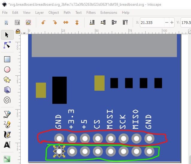
Doesn’t look like it got properly fixed. Do you have one of these boards? I suspect the reason that I didn’t fix it is that there is no documentation on what the pins do. Are the second set of pins connected to the first set or are only one set active? The pins circled in green here have connections, but the ones circled in red do not. On the actual card are the two sets of pins connected together or are only one row or the other active (and if so which row?)
I think this part should do it. I looked at some of the pictures for similar modules and it looks like the two sets of pins connect together (which is how this part is configured.)