Rather than repeating info I’ve previously posted, look at my most recent posts re making PCB’s.
the Upshot:
The PCB svg is not the same as a Part svg.
The PCB svg does not have copper layers.
I opened your file and recommend starting over as the time/effort to correct what you have will be inefficient.
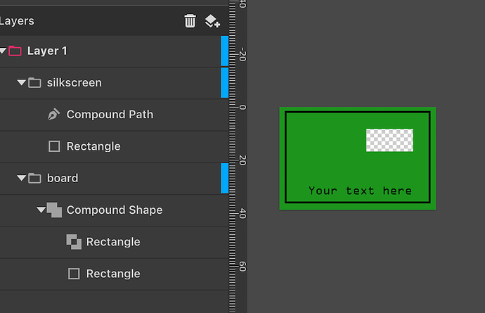
Helpful (I hope) is screenshot of a basic PCB svg layer setup… Not important is the ‘compound’ shape (which is just a different word for a Path… Don’t fuss about that. What is important are the Layer names
If you redo it and need further help, having understood my post’s, we’ll have a common foundation of understanding to solve your problem.
And, yes, you can copy&paste elements from your current file into the correct layers in a redo (thus saving about two minutes of work…)
Lastly, the SVG can be made with a text editor (which is all an SVG is, a Text file). Thus, while most all drawing apps that export SVG’s are useable (to certain degrees), they can (and do) add stuff Fritzing can’t handle so, best to keep it simple. Especially for a First-Time. So, make a very basic PCB, after success, get to where you want to be in the next step’s…
[EDIT ADDED] If you’re trying to make a ‘Part’ (Parts have a PCB but, not the Board’s PCB) take a look at most any Part. For ref, here’s my microSDcard part as an example (and Peter has posted many helpful parts to look at) http://forum.fritzing.org/t/micro-sdcard-part/5866/4
