Hello there!
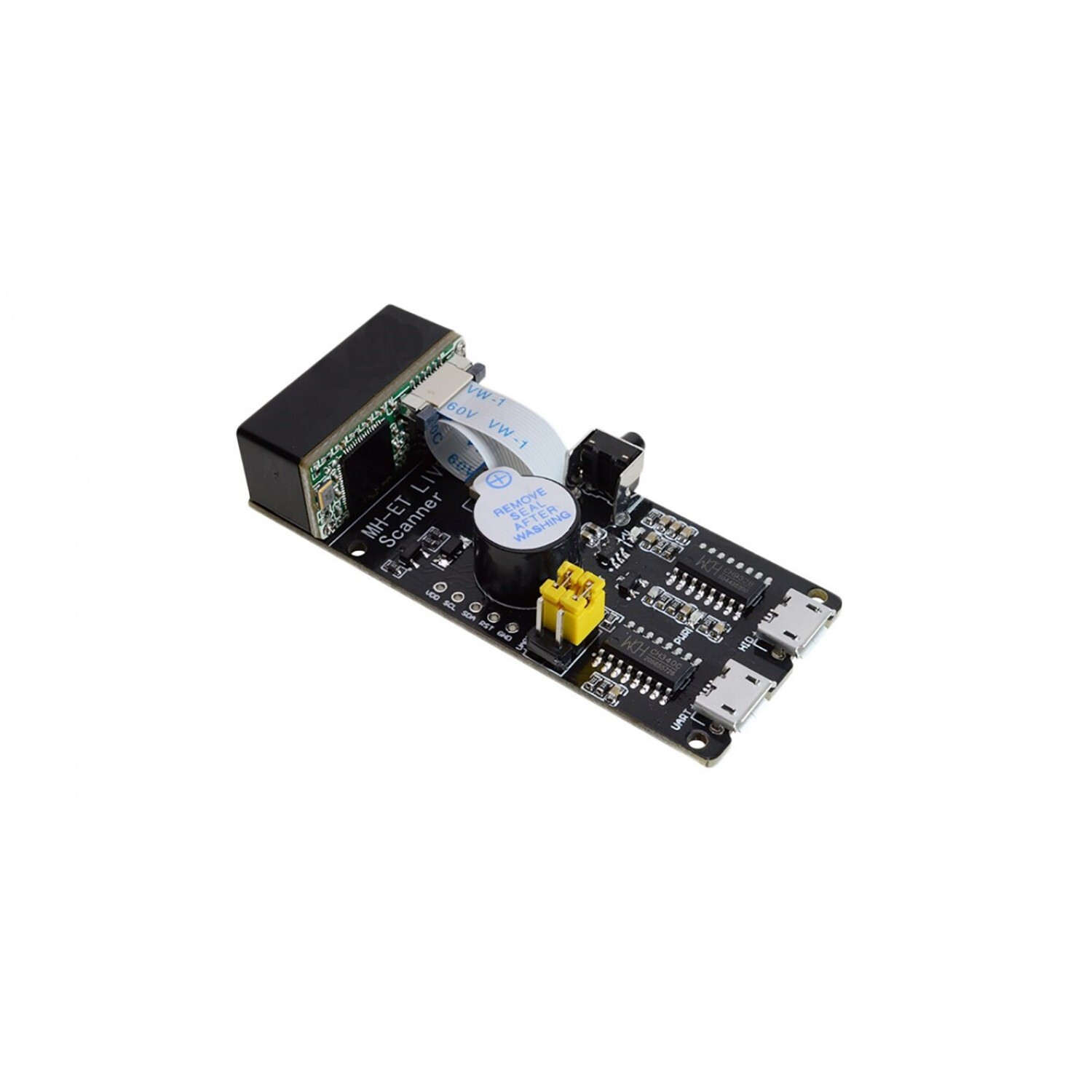
I am trying to find a schematic for this barcode scanner:
Kind regards
Not enough information to even get started. A web site the part can be ordered from “might” have a datasheet, but that usually only (at best) includes information on how to connect to and communicate with the board. That (with physical dimension information) would be enough to create a Fritzing part (with schematic view), but not a schematic of the electronics on the board. In general, only the manufacturer has the full schematic. Unless it is open source hardware, then the schematic could be published as well.
Well, I do have some information about the board and the connections, but I just don’t know how I could make a part out of it. Do I make so that other people can try make it?
Are you looking for a schematic for the board, or a Fritzing part for it?
For the part, something like a data sheet is needed. That includes the physical dimensions of the board, and where and what each of the external connections are. That appears to have a couple of USB connectors, and maybe some jumpers. Likely no PCB view is needed. It does not look like it is soldered onto a pcb. Maybe mounted on, but the electrical connections look like just the USB. It is those details that are needed to create a Fritzing part.
If you want to learn to make parts yourself, these two sets of tutorials apply to the current versions of Fritzing (most of the others are for older versions of the software.) Using Eagle2Fritzing is more difficult yet (for starters you need a Fritzing development environment to build Eagle2Fritzing!) If you need a small number of parts, it is easier to convince one of us that know parts making to make them for you. That said we are always willing to help people to make parts as everyone benefits from more people willing and able to make parts.
Since its primary output is USB, it isn’t going to be all that useful as a Fritzing part. Typically in Fritzing parts USB is not a connection. It is possible to make a part with USB connectors but they won’t connect to a typical Fritzing CPU and thus the connection won’t show up in either schematic or pcb. A breadboard only part is possible (there are a couple of USB breadboard cable parts around) though. It isn’t clear from the data sheet what the connectors on the board or the jumpers do. There is enough information in this document to make a part:
https://maxelectronica.cl/index.php?controller=attachment&id_attachment=161
As noted here in the top review, there is an i2c slave interface but no documentation on how to use it. He also wasn’t impressed with how well it worked.
As noted a part can be made for breadboard only if desired.
Peter
Please share more information about it.
There isn’t more information to share. As noted in the post above a Fritzing part isn’t particularly useful and there doesn’t appear to be more information than the data sheet listed above available.
Peter