I can’t find any useful information about the Mega2560 R3 Pro Mini, no datasheet no info no explanation of pinouts, and I don’t have a sample to check. This was made entirely from online photos and guess work, so you need to throughly check it before production because I can’t verify it’s accuracy.
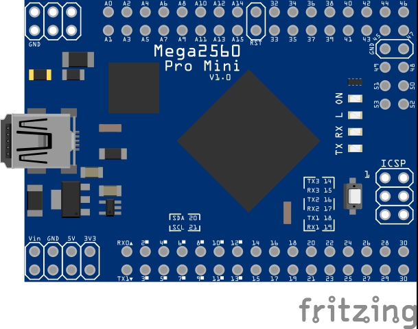
From photos it looks like a compact version of the official Arduino Mega2560, with it’s better Atmega16U2 chip, but the DC power supply has been removed. Other photos show it plugs into prefboard, so I assume it’s 21 x 15 pins on a 0.100" pitch.
Introduction:
This Meduino Mega2560 Pro Mini board is a small version of the Mega2560 board. It’s completely compatible with the original Arduino Mega2560. For the original Mega2560 it has a big board size, some time it maybe not easy to embed it into your system, the Meduino Mega2560 Pro Mini board will be more easy for embedding it into your system. It’s cute and small size.
Features:
Completely compatible with original Arduino Mega2560
Pin pitch: 0.1 inch
Size: 5.42cm*3.68cm
With Atmega16U2 chip as the USB to Serial converter
5V working voltage.
Input Voltage:7-12V
Analog Input Pins: 16
Digital I/O pins: 54
V1.0 - Mega2560 R3 Pro Mini
There are versions without headers, but this the version with female headers attached to the underside.
EDIT : My part is probably wrong - I don’t have one to check -, so use the one in the post below.
EDIT EDIT - Of course check if a newer one appears, but this is the LINK to current correct part 17th Feb 2019 below - Mega2560 R3 Pro Mini - #18 by vanepp
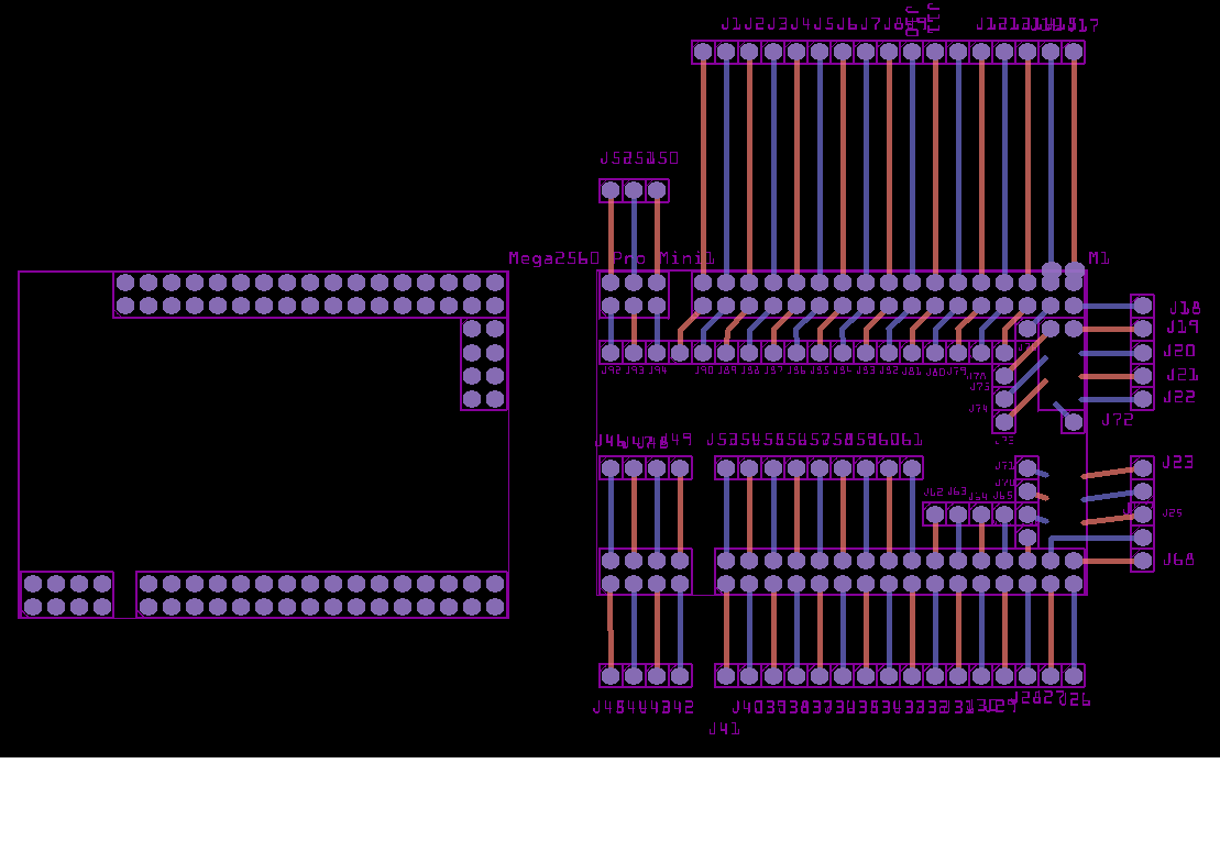
Thanks for putting in the effort. I found an issue. It doesn’t translate well to GERBER format. Pin4 48-51, GND, MISO,…(6 pins on the right).
Unfortunately I found this out after sending my PCB off to fabricate . I only relied on the PDF/SVG output, which look good. All good. I learned my lesson to always check with a GERBER viewer first.
I’ve attached a screencapture from a GERBER file viewer of what it actually looks like.
I don’t have the part, nor could find a datasheet, so I asked people to check it before use because I couldn’t verify it.
Mine was 0.100" too wide so I removed it - it doesn’t have the gerb error -, so I left it to someone with an actual board. He added bits I don’t know about, like a 6pin and 8 pin and 6 holes. I can guess the 6 and 8, but I don’t know where the 6 holes go as they don’t look to be on a 0.100" grid. I don’t think I can do anything without the part.
Really those other pin headers shouldn’t be on the PCB because people use it as a template for a shield, and all those extra holes will be drilled in the shield.
The pcb svg has translates (probably moved while grouped). They will usually screw up gerber creation. I’ll remove them and see if that corrects things, if it does can you check the resulting gerber (I don’t have one either)?
I think only the 8 pin header needs to be fixed, the other 6 pin top left and ICSP probably shouldn’t be there because they are just for jumper wires. Then again I don’t have one, so who knows.
Unfortunately the entire part has a translate 90 (all pads) and it looks like its a case of remove it and manually change them back as an ungroup doesn’t fix it.
OK here is an interrum fix. There are still problems in schecmatic (missing terminalIds and breadboard (missing layerId) but pcb is now generates what appear to be correct gerbers. If you could check it against a real board that would be appreciated. I’ll fix the rest of the problems tomorrow.
Edit:
replaced by the Mega2560 R3 Pro Mini_fixed.fzpz below
Thanks @vanepp, I haven’t checked the updated version yet but will check tonight. @Old_Grey, I tested the blue one with the ATMETGA16U, not CH340 chip, about 36.8mmx54.2mm and it fits perfectly.
Please hold off on that til I get this fixed. I’m just cleaning up schematic, but won’t (right now) renumber it so as to not bread current sketches. After that is done I’ll create a new part with pin numbers in sequence (like most Arduinos these are not) and would prefer new parts to be cloned from that so they are correct going forward.
OK, here is a properly updated version of this part. Fair warning, something I managed to do in the test sketch has managed to offset the silkscreen in the gerbers (for only the test sketch, just a part has the silkscreen correct) which I can’t see any reason for so I think the part works. If I get ambitious (or bored or frustrated with development ) I may fix this properly and renumber the pins. As it stands the pin numbers are not contiguous and that usually causes problems with the hover on the pin and it displays the description code although in a quick test I can’t see it happening. The down side to making this change (and why I didn’t do it here) is that it will break all existing sketches. This may be good enough, we will see.
Here is the fixed part:
Edit: replaced with a corrected version:
Edit2: add the VTP pin to the 5V bus
Edit3: removed RST from bus as they are all seperate, centered the usb connector and CPU chip in breadboard. Waiting to see if more bus changes are needed.
Edit4: (may be a record ) Fix one pad in pcb that was off by 0.25mm
edit5 Mar 9 2021: Corrected pins D2 and D3 in schematic which were reversed in the original part, so schematic was wrong.)
I can’t get the part imported - part already loaded problem that I can’t seam to fix -, but the 8 pin header and 6 holes are still faulty.
My orig part on the left is fine, so I don’t know what the guy did to damage it.
Damn! Last night and earlier this morning the silk looked fine in Fritzing but was offset in gerbv by about 1/2 inch, so the border around the mega pins was in the wrong place. I just reloaded the sketch in gerbv to print out the problem and now its fine! That’s why I didn’t post this last night when I finished it. Don’t know what that is about, but looks like a gerbv issue rather than Fritzing although I’ve never seen it before and can’t reproduce it now. The “part already loaded” error can be fixed by deleting the part in the mine parts bin (I think you have to restart fritzing to get it to actually delete) and if that doesn’t work, either clearing the user directories or remove the fzp file for the mega in My Documents\fritzing\parts\user.
 . I only relied on the PDF/SVG output, which look good. All good. I learned my lesson to always check with a GERBER viewer first.
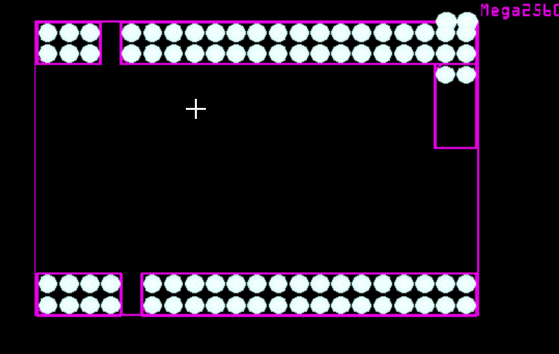

 ) I may fix this properly and renumber the pins. As it stands the pin numbers are not contiguous and that usually causes problems with the hover on the pin and it displays the description code although in a quick test I can’t see it happening. The down side to making this change (and why I didn’t do it here) is that it will break all existing sketches. This may be good enough, we will see.