I don’t have one, so I’m a poor one to say. The fellow who has one would probably have a better answer than me.
Peter
I don’t have one, so I’m a poor one to say. The fellow who has one would probably have a better answer than me.
Peter
Do you want my original 0.100" part, because it’s not broken like that one.
I hope that guy didn’t use the interim part.
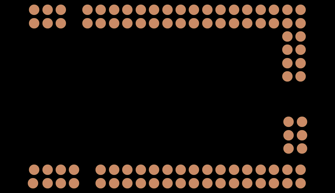
That looks to be the original part (which had translates in pcb), the interrum fix part I posted a couple of days ago works correctly as far as I can see. I just downloaded the one posted and tried it. From gerbv:
I wonder if the svg for the original hasn’t been deleted from your my documents svg directory (because I didn’t change the file names) and you are getting the old version?
Peter
That version was in the test sketch. I tried renaming the internal .fzp file of the fixed part but it said part already in bin, so I didn’t test that one.
EDIT - Got the fixed part in and it’s ok now.
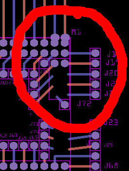
The 16U ISCP header would be great because they PCB routing keeps trying to use them as GND, since they are all marked as GND.
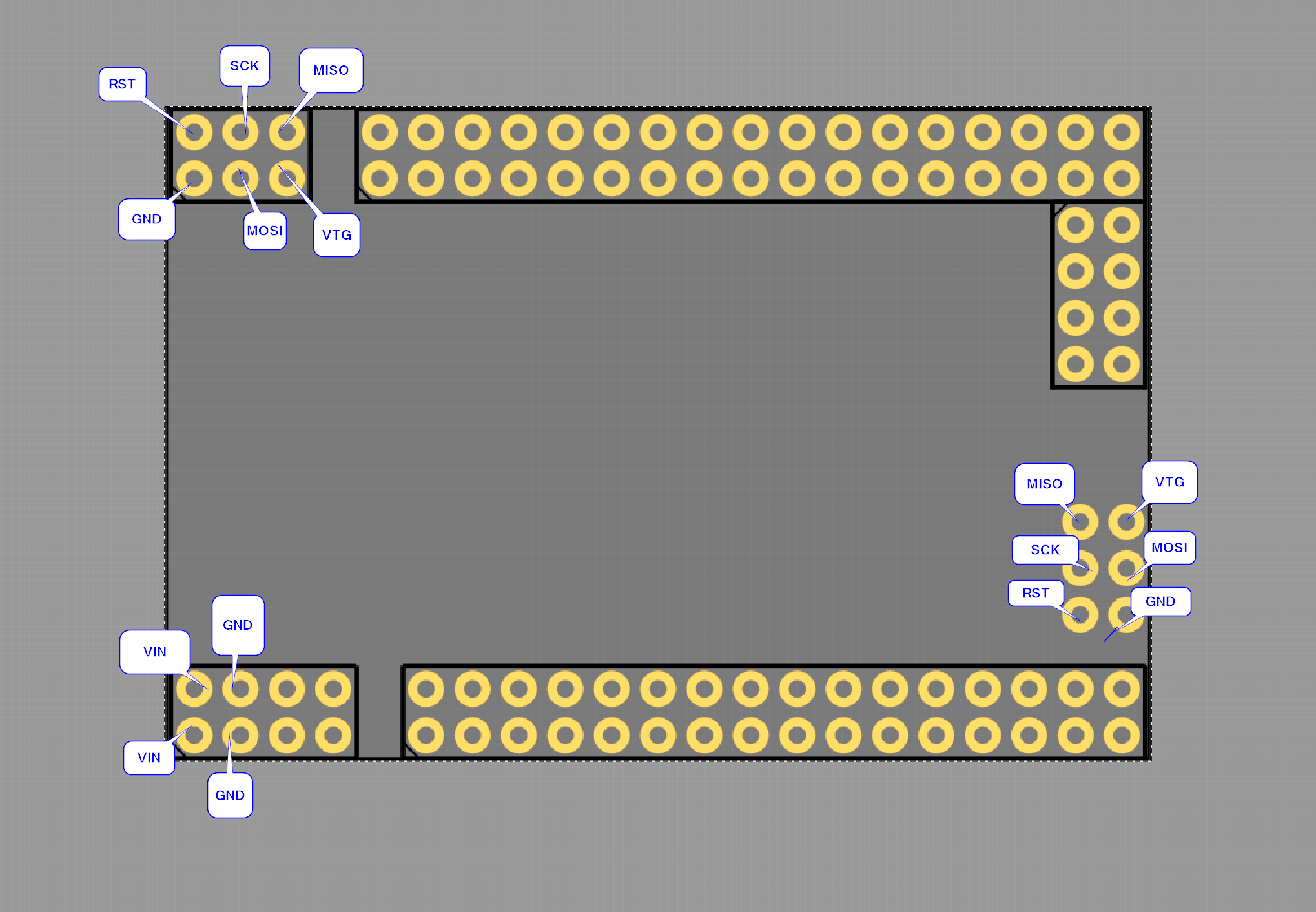
382 - RST
383 - SCK
384 - MISO
385 - GND (Correct)
386 - MOSI
387 - VTG
The problem is people use that board as a template for a shield, and the empty holes in the shield would take up extra area that you could use to lay tracks. If you look at all the Arduino boards the ICSP don’t work.
On the other hand, if you want to make a tutorial on how to connect a ICSP to this board you would want them to work.
I’m more inclined to the first.
OK, I’ll change it to match your pinout. Old_Grey: there isn’t any reason to not have two parts, one with the ISCP and one without. Then the user can choose which to use. I’m inclined to do the renumber then split them that way. Is it only the ISCP connector you think should go? On the shield version we could move the pads to silk screen so they could at least have holes if they needed too.
edit: Is it a correct assumption that these share the same named pins else where and thus should be bused to the other pins?
Edit2:
OK now I’m really confused  the pin numbers above are wrong, the pins only go up to 386, so I pulled up the boards referenced by Old_Grey but they don’t match the PCB layout. There is a reset switch over the left side set of 6 pads (unless it is connecting to the pads? Also from the picture the board I made seems to be wrong. The two end connectors (the 6pin and the 8) look to be reversed on the Fritzing board. Also the mounting holes are missing (even if they are only on the silkscreen as usual so you can drill the hole if you want). Ah! This board doesn’t seem to be either of those listed but this third board which does match this pcb layout:
http://wiki.epalsite.com/index.php?title=Mega2560_Pro_Mini
although then we are missing the usb connector that sticks out past the end of the board in silkscreen. There are no mounting holes in this one. I should probably add this as the url so people know which board this part is for as well (when I checked that is the site with a wrong url that is listed, I’ll correct that too). OK there isn’t enough info on the pinout diagram to fix this so its
up to you with a board in hand :-).
indent preformatted text by 4 spaces
top left in pcb view, ICSP connector for 16u2:     top right

381 382 383                               367 gnd?  374 gnd?
  ?   ?   ?                               386 19    373 48
384 385 386                               369 51    372 58?
  ?   ?   ?                               370 53    371 57?

                                          ISCP mega

					  375 ? 376 ?
                                          377 ? 378 ?
                                          379 ? 380 ?
If you can fill in the ? marks with a pin name and what else it connects to I’ll correct the board to match. This of course assumes this is the board you have …
Peter
I’m not too worried about the ICSP, just leave it.
The left ICSP is for the 16u2 chip, and the right ICSP is for the MEGA2560 chip, so I suppose they should not be connected. Not sure there is a PWR, but the single GNDs should be common.
Right but they are all labeled ground at the moment, which is incorrect.
They are also all bused as ground which is more of a problem.
Peter
OK I deleted the interrum version and updated the link to Mega2560 R3 Pro Min_fixed.fzpz above with a new (hopefully correct) one. One issue may be that VTG on the 16U2 is not in the 5V bus and I think it perhaps should be. If someone can confirm that it should connect to 5V I’ll change it once again.
Peter
The official MEGA and UNO have ICSPs in the same orientation and roughly in the same position, and their pin orders are as you have them.
Your VTG pin says it’s 5V - 3/4 of the way down this page -.
OK I’ll add that last pin to the bus and reload yet again.
Peter
Damn, we learnt something new, ie maybe a bug.
I had the old faulty offset 8pin part in MINE bin, that has the same internal ID as the fixed part in Van’s test Sketch. But when I opened that sketch FZ took the faulty part from MINE bin, rather than the fixed part from temp bin inside the sketch.
BTW. I know this might be common knowlege howver I neglected to specify that the RST pins on the ISCP are not on a common bus. Just wanted to clarify.
Yeah it’s only the 5V and the GND that are common across the board, I checked my MEGA last night.
Can you can check the new part is ok, so we can sign off on it. I think Van put it in the old post above.
I expect that is a bug. It should have tossed a “part is already in Fritzing” type error, or kept track of which bin it was using although I don’t think that would work because duplicate moduleIds will cause problems in the code, it is assumed to be unique.
Peter
Wasn’t common knowledge to me , I’ll check and see if they are bused.
Edit: looks like it wasn’t common knowledge to someone else too one reset is not bused but the other is. I will remove it and update the part yet again.
Edit2: While removing that bus I see there are scl and sda buses defined but they have no members (and thus aren’t busing anything). Should some set of pins be bused?
Peter
Looking at an original MEGA from the bin pin 20 and 21 are connected to two unlabelled pins, but I don’t think this Mini has those. It does have the 53 IOs, but I’m not sure.
I just noticed when the guy shrunk my BB view 0.100" on one side he didn’t move some of the parts down to make it symmetrical. Too late now, because it’s too hard to relabel each pin again - done that many times -.