Thanks @vanepp, I haven’t checked the updated version yet but will check tonight. @Old_Grey, I tested the blue one with the ATMETGA16U, not CH340 chip, about 36.8mmx54.2mm and it fits perfectly.
Please hold off on that til I get this fixed. I’m just cleaning up schematic, but won’t (right now) renumber it so as to not bread current sketches. After that is done I’ll create a new part with pin numbers in sequence (like most Arduinos these are not) and would prefer new parts to be cloned from that so they are correct going forward.
OK, here is a properly updated version of this part. Fair warning, something I managed to do in the test sketch has managed to offset the silkscreen in the gerbers (for only the test sketch, just a part has the silkscreen correct) which I can’t see any reason for so I think the part works. If I get ambitious (or bored or frustrated with development ) I may fix this properly and renumber the pins. As it stands the pin numbers are not contiguous and that usually causes problems with the hover on the pin and it displays the description code although in a quick test I can’t see it happening. The down side to making this change (and why I didn’t do it here) is that it will break all existing sketches. This may be good enough, we will see.
Here is the fixed part:
Edit: replaced with a corrected version:
Edit2: add the VTP pin to the 5V bus
Edit3: removed RST from bus as they are all seperate, centered the usb connector and CPU chip in breadboard. Waiting to see if more bus changes are needed.
Edit4: (may be a record ) Fix one pad in pcb that was off by 0.25mm
edit5 Mar 9 2021: Corrected pins D2 and D3 in schematic which were reversed in the original part, so schematic was wrong.)
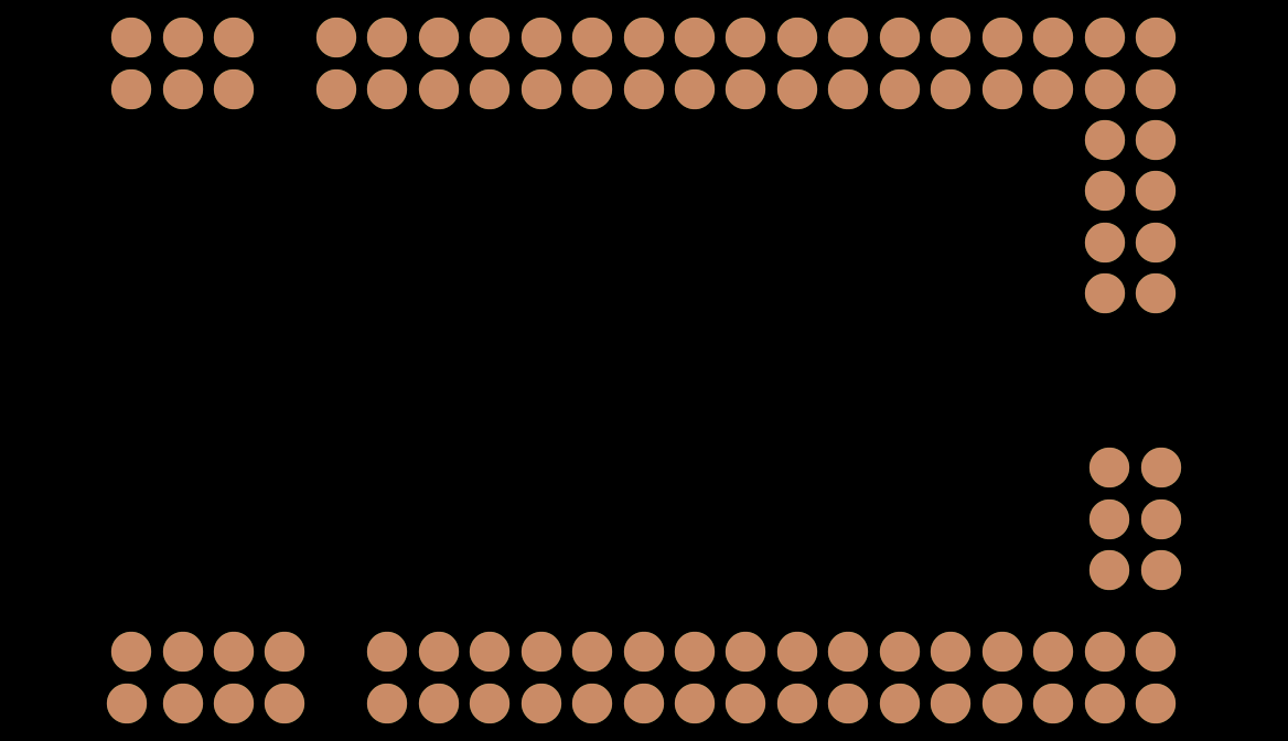
I can’t get the part imported - part already loaded problem that I can’t seam to fix -, but the 8 pin header and 6 holes are still faulty.
My orig part on the left is fine, so I don’t know what the guy did to damage it.
Damn! Last night and earlier this morning the silk looked fine in Fritzing but was offset in gerbv by about 1/2 inch, so the border around the mega pins was in the wrong place. I just reloaded the sketch in gerbv to print out the problem and now its fine! That’s why I didn’t post this last night when I finished it. Don’t know what that is about, but looks like a gerbv issue rather than Fritzing although I’ve never seen it before and can’t reproduce it now. The “part already loaded” error can be fixed by deleting the part in the mine parts bin (I think you have to restart fritzing to get it to actually delete) and if that doesn’t work, either clearing the user directories or remove the fzp file for the mega in My Documents\fritzing\parts\user.
That looks to be the original part (which had translates in pcb), the interrum fix part I posted a couple of days ago works correctly as far as I can see. I just downloaded the one posted and tried it. From gerbv:
I wonder if the svg for the original hasn’t been deleted from your my documents svg directory (because I didn’t change the file names) and you are getting the old version?
That version was in the test sketch. I tried renaming the internal .fzp file of the fixed part but it said part already in bin, so I didn’t test that one.
The problem is people use that board as a template for a shield, and the empty holes in the shield would take up extra area that you could use to lay tracks. If you look at all the Arduino boards the ICSP don’t work.
On the other hand, if you want to make a tutorial on how to connect a ICSP to this board you would want them to work.
OK, I’ll change it to match your pinout. Old_Grey: there isn’t any reason to not have two parts, one with the ISCP and one without. Then the user can choose which to use. I’m inclined to do the renumber then split them that way. Is it only the ISCP connector you think should go? On the shield version we could move the pads to silk screen so they could at least have holes if they needed too.
edit: Is it a correct assumption that these share the same named pins else where and thus should be bused to the other pins?
Edit2:
OK now I’m really confused the pin numbers above are wrong, the pins only go up to 386, so I pulled up the boards referenced by Old_Grey but they don’t match the PCB layout. There is a reset switch over the left side set of 6 pads (unless it is connecting to the pads? Also from the picture the board I made seems to be wrong. The two end connectors (the 6pin and the 8) look to be reversed on the Fritzing board. Also the mounting holes are missing (even if they are only on the silkscreen as usual so you can drill the hole if you want). Ah! This board doesn’t seem to be either of those listed but this third board which does match this pcb layout:
although then we are missing the usb connector that sticks out past the end of the board in silkscreen. There are no mounting holes in this one. I should probably add this as the url so people know which board this part is for as well (when I checked that is the site with a wrong url that is listed, I’ll correct that too). OK there isn’t enough info on the pinout diagram to fix this so its
up to you with a board in hand :-).
indent preformatted text by 4 spaces
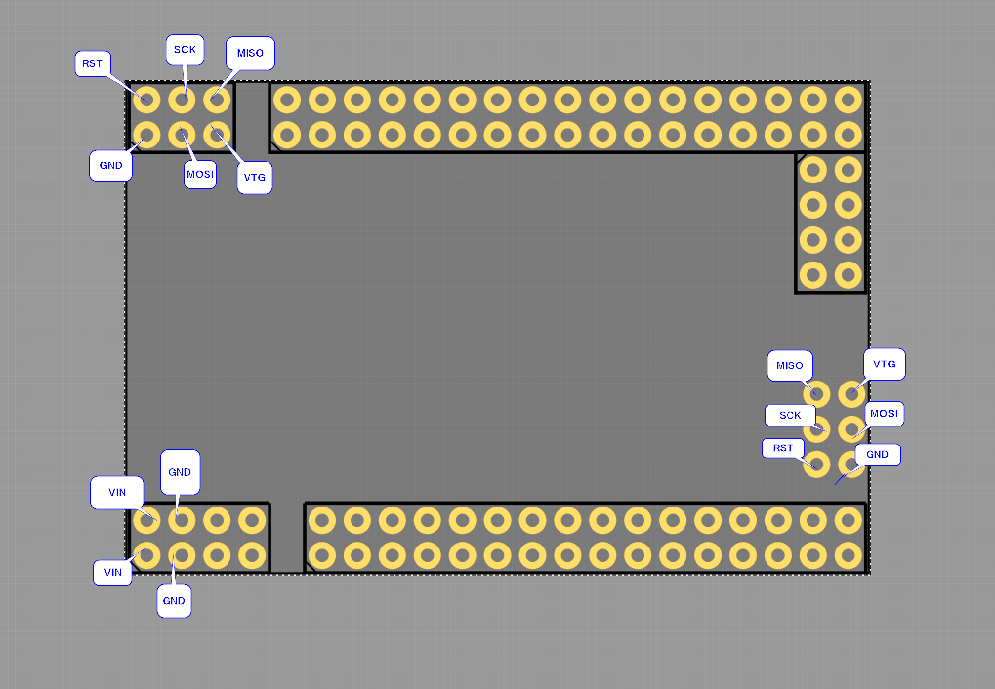
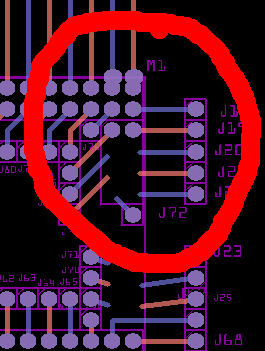
top left in pcb view, ICSP connector for 16u2: top right
381 382 383 367 gnd? 374 gnd?
? ? ? 386 19 373 48
384 385 386 369 51 372 58?
? ? ? 370 53 371 57?
ISCP mega
375 ? 376 ?
377 ? 378 ?
379 ? 380 ?
If you can fill in the ? marks with a pin name and what else it connects to I’ll correct the board to match. This of course assumes this is the board you have …
I’m not too worried about the ICSP, just leave it.
The left ICSP is for the 16u2 chip, and the right ICSP is for the MEGA2560 chip, so I suppose they should not be connected. Not sure there is a PWR, but the single GNDs should be common.
 ) I may fix this properly and renumber the pins. As it stands the pin numbers are not contiguous and that usually causes problems with the hover on the pin and it displays the description code although in a quick test I can’t see it happening. The down side to making this change (and why I didn’t do it here) is that it will break all existing sketches. This may be good enough, we will see.
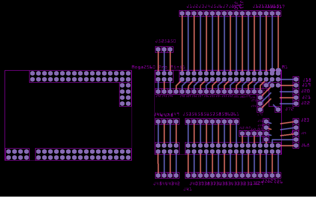
 the pin numbers above are wrong, the pins only go up to 386, so I pulled up the boards referenced by Old_Grey but they don’t match the PCB layout. There is a reset switch over the left side set of 6 pads (unless it is connecting to the pads? Also from the picture the board I made seems to be wrong. The two end connectors (the 6pin and the 8) look to be reversed on the Fritzing board. Also the mounting holes are missing (even if they are only on the silkscreen as usual so you can drill the hole if you want). Ah! This board doesn’t seem to be either of those listed but this third board which does match this pcb layout: