I made an SGV file. i just cant figure out how to get it into Fritzing.
![]()
Please help!
A google search for “fritzing part db15 connector” (which is the place to start when you need Fritzing parts that aren’t in core parts) turns up:
which has male and female VGA connectors as well as the referenced game port available.
Peter
ya, but that one has 3 rows of pins.
cant use blank ic’s eather because the pin spacing wont line up.
is that somthing that is farly simple to change?
Do you have the data sheet for the connector you want (or a pointer to where it can be found?) It is easy enough for me to make a part if I have a data sheet for the connector. Your svg has incorrect groups and pin definitions. It is also unclear whether the connector you want is intended for pcb mount or wires (the hole sizes in pcb will likely be different in the two cases.) There doesn’t currently appear to be a Fritzing part for this particular connector.
Peter
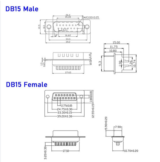
This looks to be solder tabs for wires. Assuming your svg is the spacing and hole size you want I’ll make a part from that.
Peter
Sweet!
You’re a saint!
OK here is a part that should do what you want.
db15.fzpz (8.6 KB)
it has all 3 views and pcb is a corrected version of your svg (the spacings were slightly off in your svg and have been corrected.) You may want to print out the pcb footprint at 1:1 scale and make sure it will do what you want. The holes for the wires are 0.035in and the nonconn holes will be drilled and have the copper pads.
Peter
thanks x 1,000,000,000
printing it out is a great idea. i will do that today and let you know.
I was able to print it out today and everything looks good except the holes on the sides are a little off. it looks like they need to be 33mm apart from each other. how would i go about changing this? can you direct me to any simple how-to?
It appears they are correct from the data sheet. The circle centers are 1.31in (33.32mm) apart:
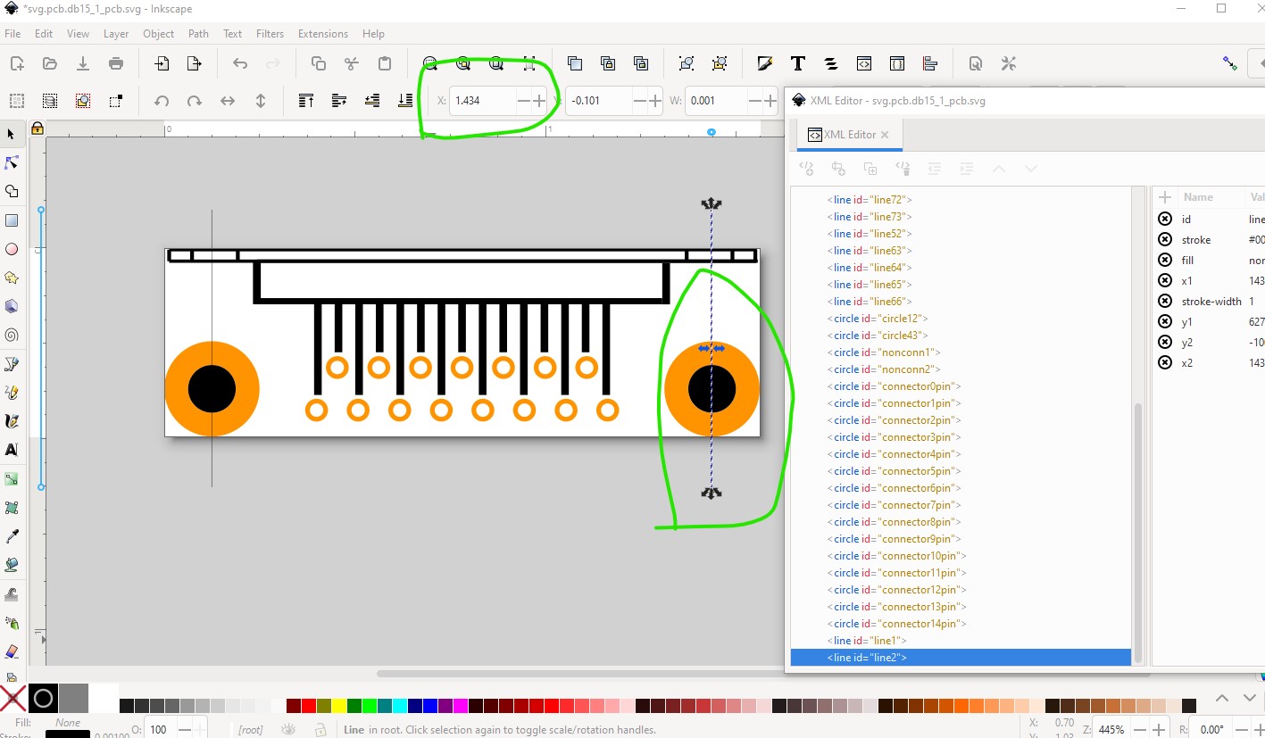
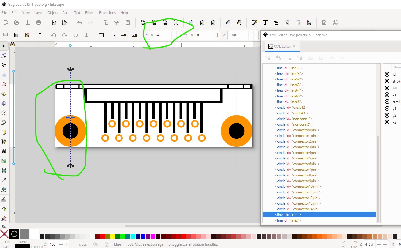
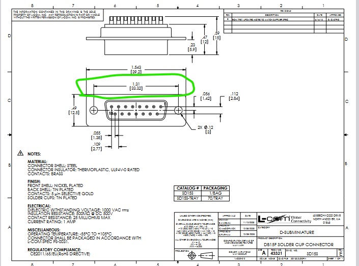
I would check that your print out is indeed 1:1 scale, if that is off so will the hole spacing be. An alternative check is to export the gerber files (which are in 1/1000 of an inch) and check the spacing in the gerber files (although that isn’t all that easy!) It also looks correct in the gerber output drill.txt file:
; NON-PLATED HOLES START AT T1
; THROUGH (PLATED) HOLES START AT T100
M48
INCH
T1C0.125000
T100C0.035000
T101C0.125000
%
T1
X022938Y011217
X009823Y011217
022938 - 009823 = 13115 (or 1.3115 in as this is in 1/1000 of an inch) which also looks correct from the data sheet.
T1C at 0.125 in is the two larger holes the x coords are the distance between them.
Unfortunately making (or even modifying) parts is not easy. This tutorial covers the steps needed and you need to run the finished part through FrtizingCheckPart.py to correct the problems that Inkscape (and probably the other svg editors) introduce for CSS compliance (which Fritzing doesn’t care about!)
Peter
Thanks for your help.
After measuring my print it appears that my print is not a perfect 1:1 ratio. So the part is correct.
I would still like to make some other parts like some simple bolt holes and the like so i will definitely be checking out the tutorial.
Feel free to ask for help (as you will likely run in to trouble!) As noted part making is complex and the rules aren’t entirely documented. Usually when Fritzing prints out a footprint the scale is correct at 1:1 (printer driver magic I expect) so I’m not sure what went wrong in your case or how to fix it. The gerber output is what the board house will make the boards from so the measurements in there will be accurate. As well if the tutorial isn’t clear please point out where and I will try and correct it (the usual reaction is parts making is too difficult I think and thus no one so far has commented …)
Peter
ok, i will document the experience and let you know if i run into anything.