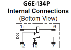
I need an Omron G6E relay in my project. There are a few variants in core parts, but not this one. The variant G5Q is available (sparkfun-electromechanical_relay) and is almost identical, apart from the pin designations are different in PCB view.
Is there an easy way to modify the core part to add new variant? Or do I have to start from scratch and create a new part?
The easiest way to create a new part IS to start from an existing part. Whether the existing is in core or not. Drag the existing part to a sketch, then right click and choose Edit (new parts editor) from the menu. If the only thing you need to change is the PCB graphics, goto that view, then export; As image; SVG. Use whatever editor (like Inkscape) to make the changes, then File; Load image for view back in the parts editor. Save that as a new part, load it into your “mine” parts bin, and ready to go.
If I used the correct existing core part to walk through the steps as I was writing the above, all that is needed is to move one of the coil connector holes. You might also want to change properties and description for the new part.
These two sets of tutorials apply to the current versions of Fritzing (most of the others are for older versions of the software.) Using Eagle2Fritzing is more difficult yet (for starters you need a Fritzing development environment to build Eagle2Fritzing!) If you need a small number of parts, it is easier to convince one of us that know parts making to make them for you. That said we are always willing to help people to make parts as everyone benefits from more people willing and able to make parts.
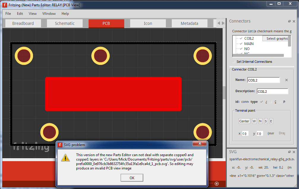
If “ALL” you changed was the pcb svg, I would have expected it to work. The red is showing that the connections are not defined (associated) correctly. If you upload the created part (fzpz file) here (7th icon from the left), we can have a look. I normally work outside of the Parts editor, so maybe swapping the svg also cleared the connector association. Or the svg editing managed to delete the connector id information in the svg. The error message is about separate copper0 and copper1 layers. Parts Editor expectes those to be nested one inside of the other (instead of one after the other).
What core part did you start from, and how did you edit the pcb image?
I exported as image as you suggested, then modified in Inkscape, saved and then “Load image for view”.
It seemed to work fine in parts editor, but when saved as new part, it didn’t work when dragged into the PCB view.
After editing, you need to ‘save’ the new part. That will create the fzpz file. Which is now a custom (user) part, instead of a core part.
If the error message in the earlier post is from parts editor, it may not have actually create the new part properly. The problem might start with the original core part. Parts can be valid without Parts Editor being able to handle them.
The screen shot above shows “sparkfun-electromechanical_relay-g5q_pcb.svg” in the Parts Editor. I opened that, and can confirm that it has separate instead of nested copper1 and copper0 layers. That is likely the source of the problems.
I did not give quite the right instructions above. Comes from avoiding (the limitations of) Parts Editor. After “Save as new part” in parts editor, the part shows up in the “mine” bin. From there, right click on the part, and “Export part” to create the fzpz file. I am working on a ‘fixed’ version of the sparkfun relay that you could use as a base for your variant. Back in a bit.
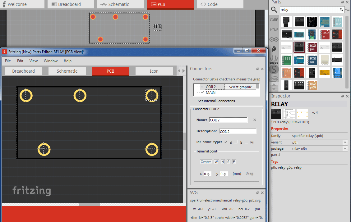
Here is a cleaned up sparkfun relay part. Download it, then open it from Fritzing to get it into your “Mine” parts bin. Right click and edit that, then as above export the pcb image, edit, reload, and save. See if that gets past the errors.
Don’t forget to save the imported parts and changes to the bin on exit from Fritzing, if you want to use the parts again later.
That is a process I do not actually use. I am comfortable with command line and text editors, so I extract the svg from the fzpz file (just unzip), edit the svg and fzp with a text editor (it is just xml), then zip it again to get a usable part. That works for me, because I know the internal file formats for svg and fzp, and it lets me do things that the Parts Editor fails with.
For future reference, you can (usually) edit the existing post to replace a bad uploaded version. Instead of adding another. That way the bad version will not accidentally get downloaded and used in the future.
If you want to share your new version, a post in the Parts Submit category of the forum works. Most searches would find it here as well. When writing a post for a submitted part, include details about where it can be found. Provide information that is likely to match if someone is searching for the part file.
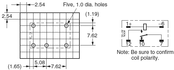
I’m not intending to produce a pcb, so I’ve not checked the dimensions of this part. The datasheet has dimensions in mm, but it appears to be standard 12 pin DIP.
Opening the core part in Inkscape shows this for the pins.
I don’t understand what units the dimensions are in here. It doesn’t appear to be mm or inches. I also noticed that the viewbox is different to the width & height, why is this?
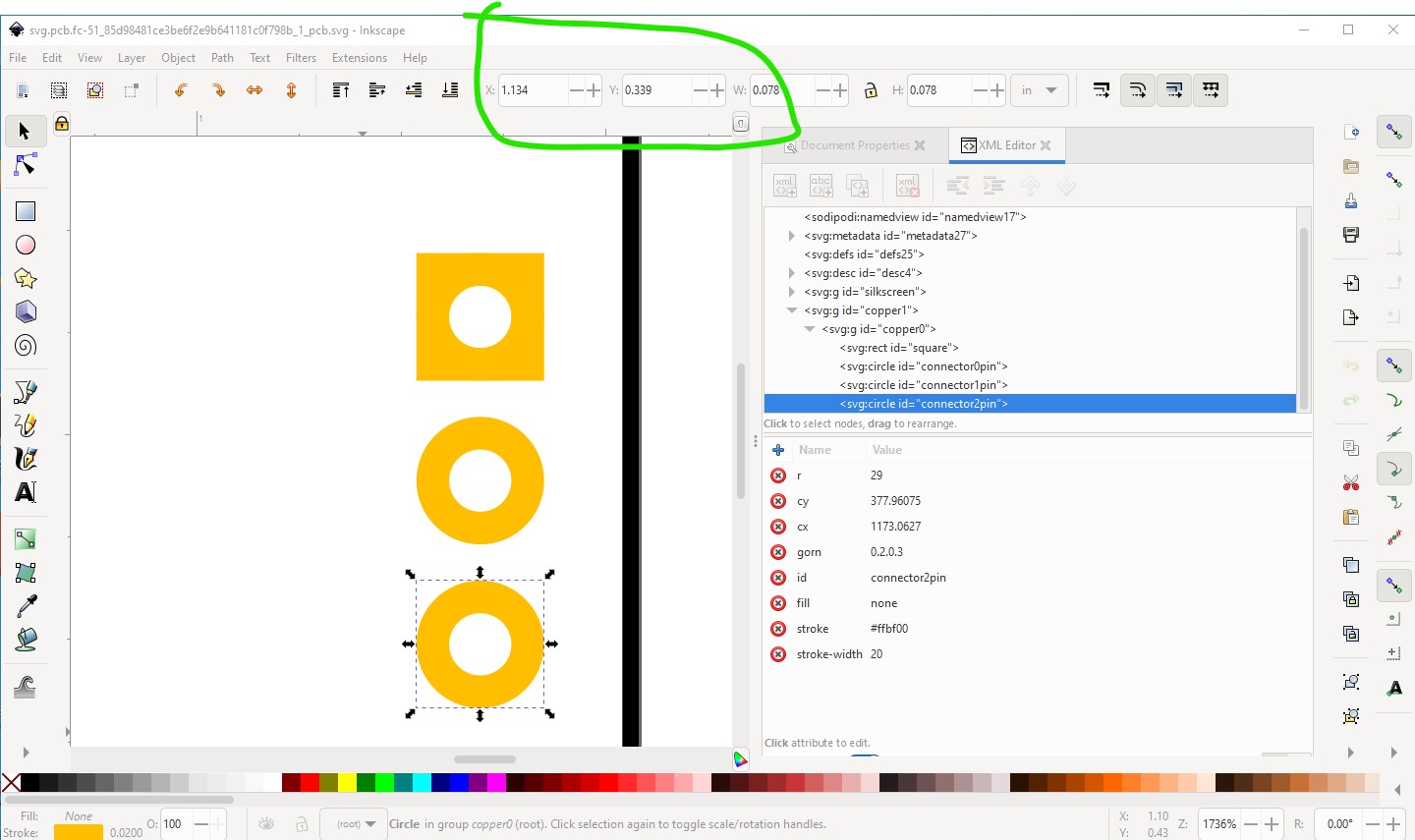
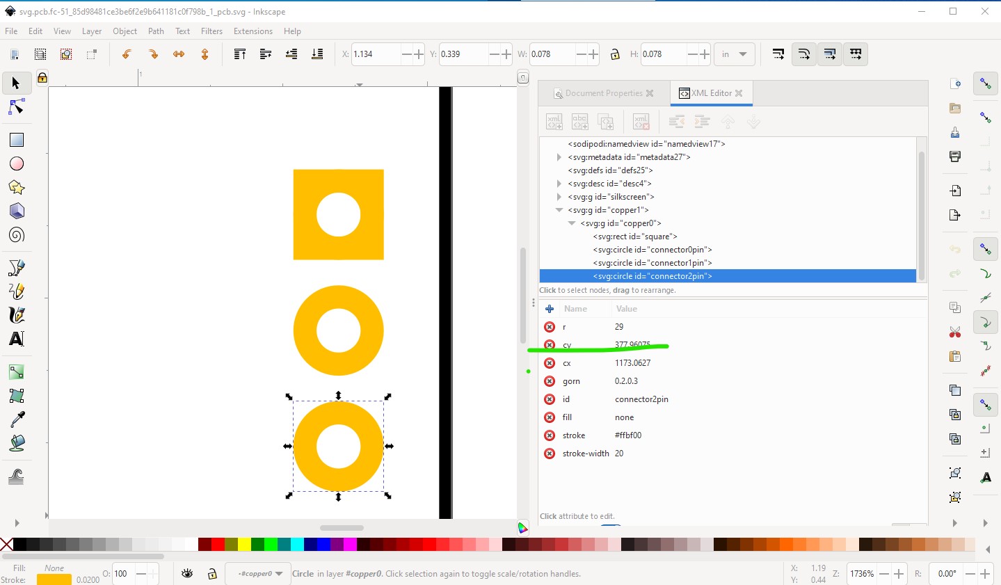
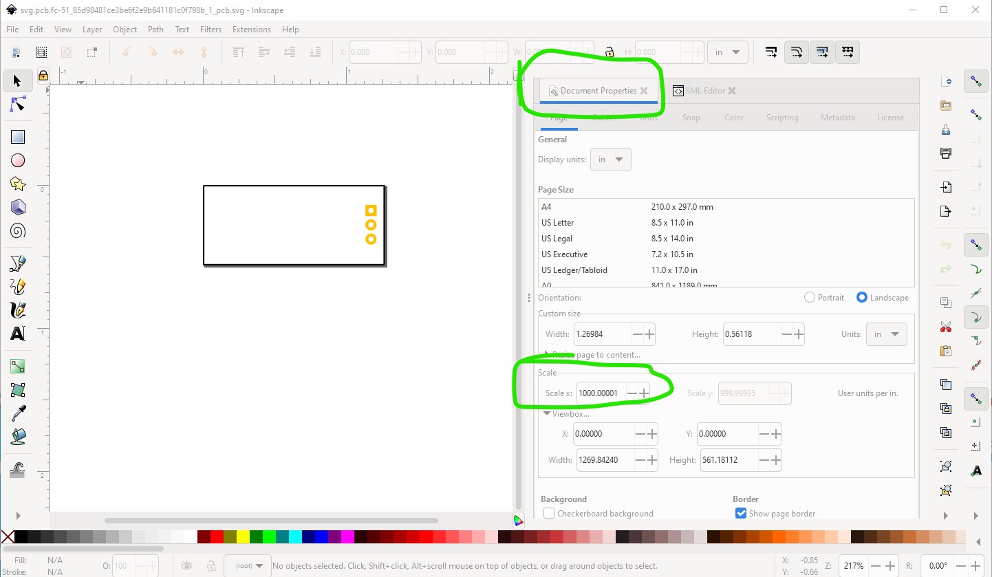
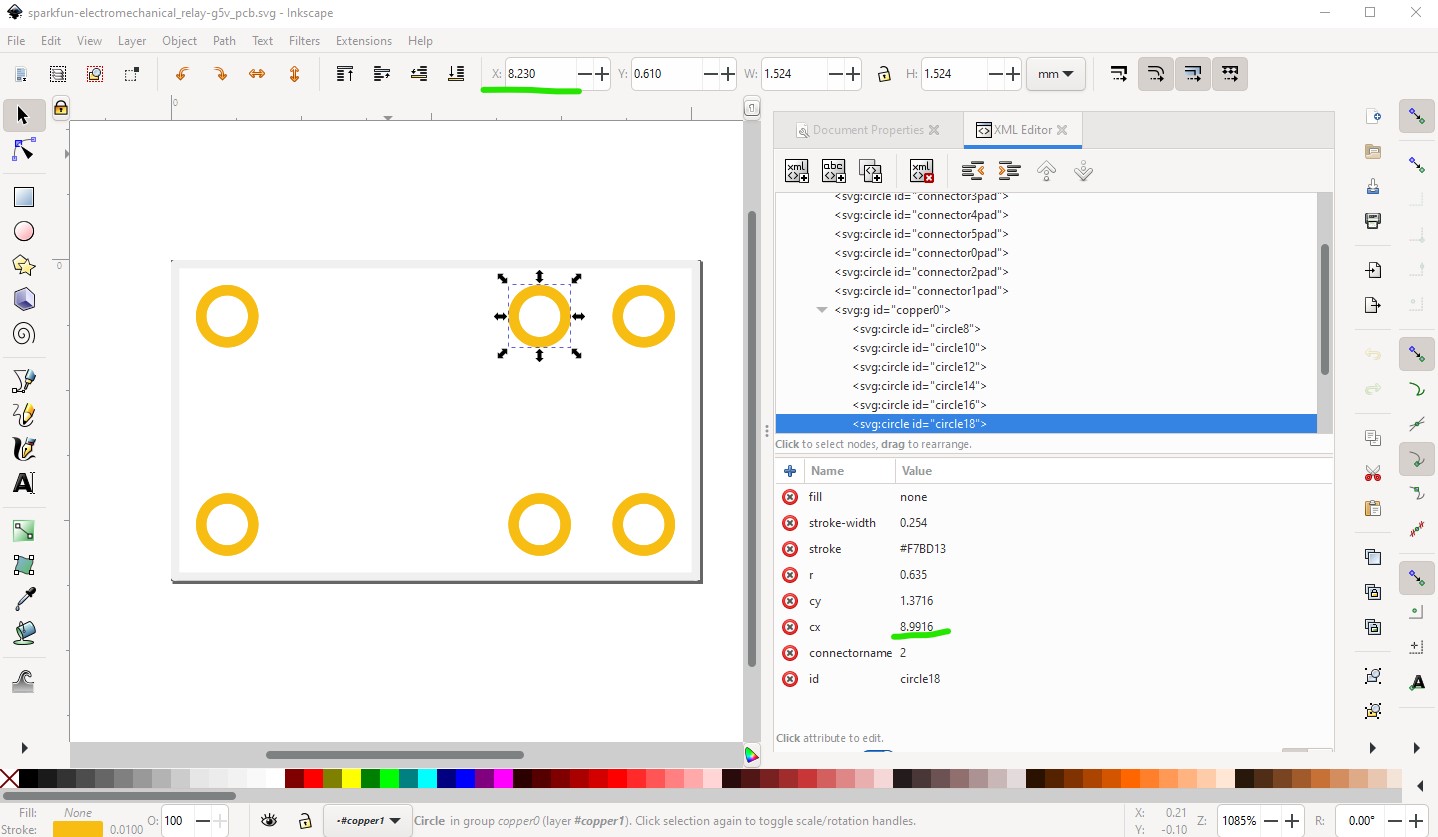
The units are in drawing units (which depends on the viewbox.) If the scale is 1000 (in the latest Inkscape, 10.41667 in earlier versions) the units will be 1/1000 of an inch. Otherwise they are proportional to viewbox size. The easiest solution is to set the tool bar to in or mm remembering that the start is the top left of the drawing element, so the x and y spacing should be exactly 0.1in in the tool bar display. An example using Inkscape 1.1.2 (where scale is 1000)
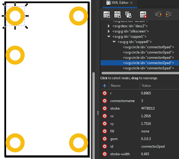
again modulo floating point roundoff issues, cy goes from 277.96075 to 377.96075 (exactly .1 in in this case) referenced to the top left corner of the drawing element (not the center of the circle!)
edit: In turn the start is the top left of the view box as 0 0.
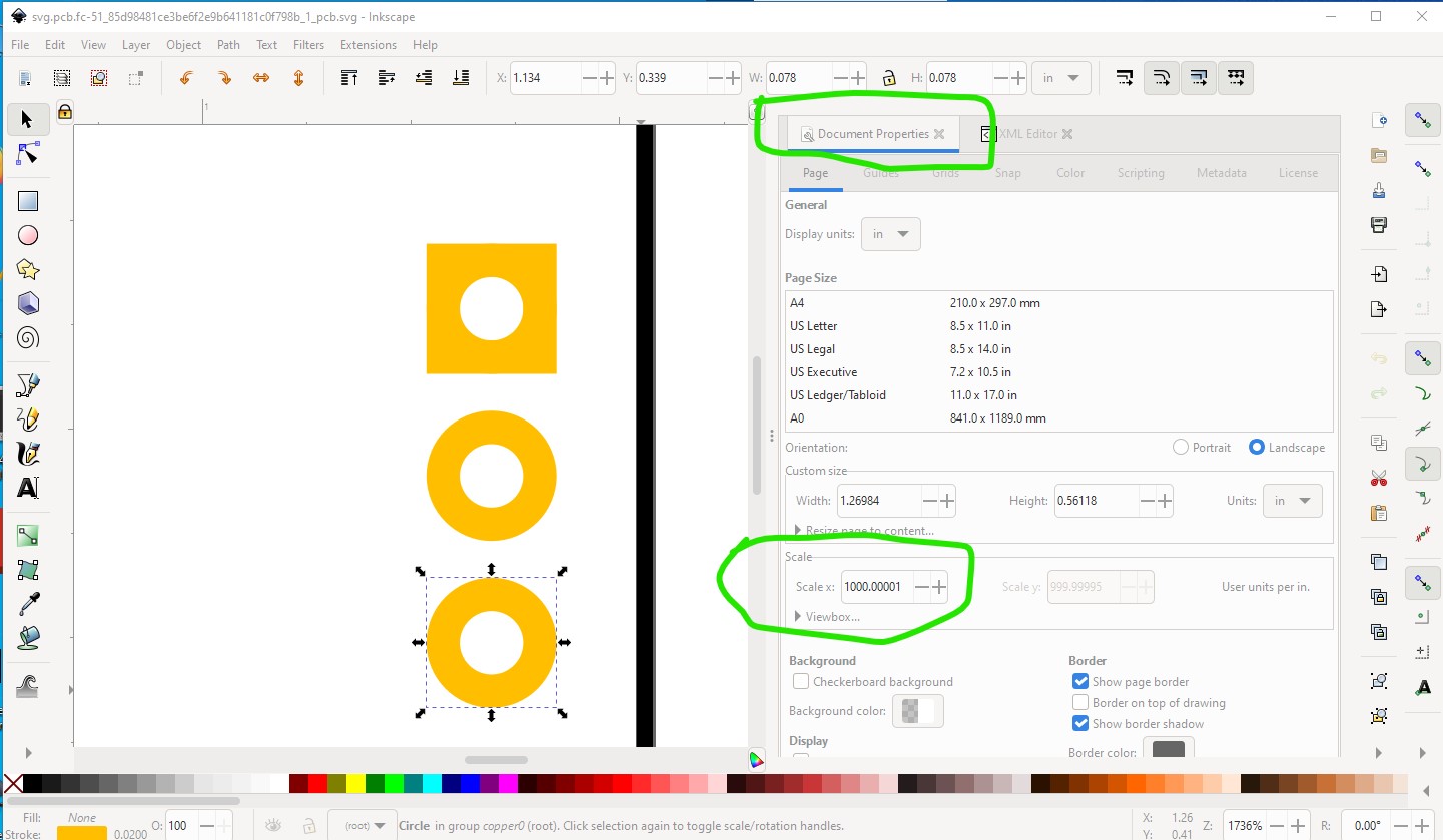
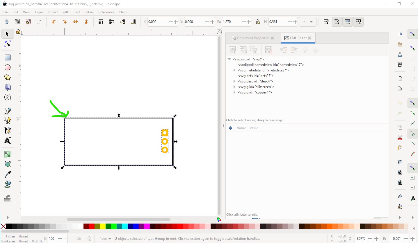
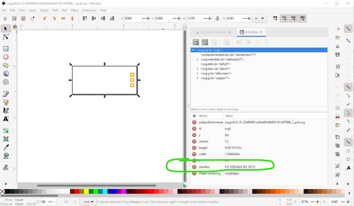
the green circle at the top is the document properties selector and the circle in the middle is the scale (set to 1000 here.) Hitting Edit->select all will cause the view box to be displayed in the tool bar x y (1.27in by 0.561in here)
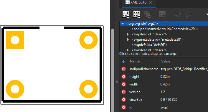
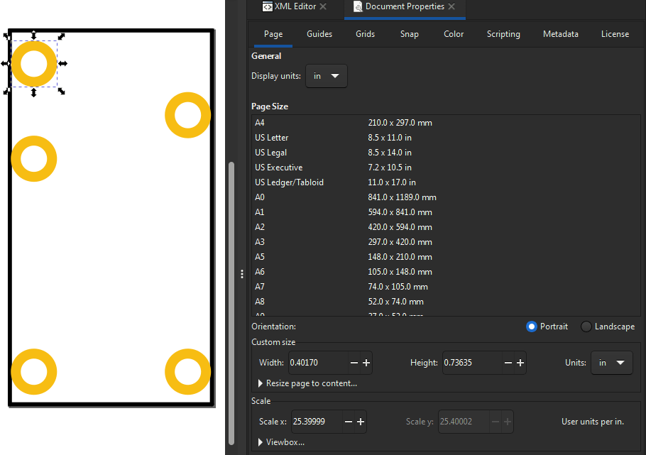
1269.8424 561.18112 which is 1.27in (in thousands of an inch) by 0.561in (again in thousands of an inch) and thus the coordinate values in the xml editor window are in 1000th of an inch increments relative to the start of the viewbox. The graphics standard specifies the 100:1 ratio for view box to actual document size to get drawing units in 1000th of an inch. Any scale will work, but the internal units in xml editor will not be 1000th of an inch. The viewbox above is correct. The height is 0.32in and width is 0.42in and the view box is 420 320 (100 x width and height) so internal units should be 1/1000 of an inch. That said many parts in core are not at the correct scale, and some of the parts create by the parts factory are not at the correct scale because it doesn’t make any visual difference to Fritzing and (I suspect but don’t know for sure) that the viewbox recommendation in the graphics standard doc was a late addition and wasn’t ever retrofitted to either the parts factory or core parts. We should do both things, but haven’t yet. With the correct scale (or without it, as it is possible to do the transformation from the viewbox to height width value) FritzingCheckPart could (but doesn’t currently) check for proper pin spacing in at least some circumstances.
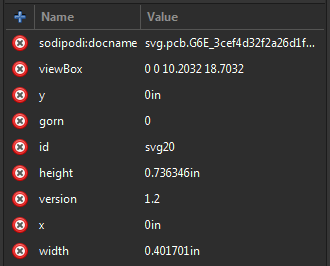
I see that your viewbox has the same numeric value as the width & height (give or take a decimal point). This is what I was expecting in my example and didn’t understand why it would be different.
Below is the Document properties for the core part…
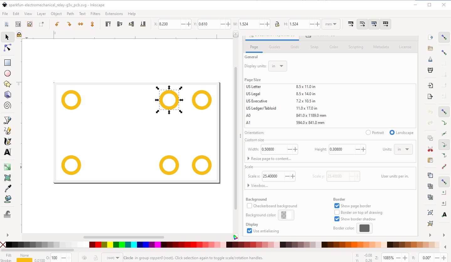
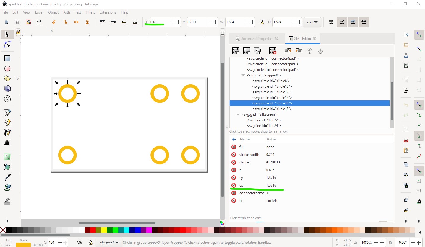
If I subtract the first x coord from the tool bar by the second, I get 7.62mm in x (8.230 - 0.610mm.) That matches the difference in xml editor 8.9916 - 1.3716 = 7.62 but there is an offset because the low X should be 0.610 not 1.3716 according to the tool bar. I don’t know why the offset is there.
Thank you, it makes sense now. I don’t really see why they didn’t just keep everything in inches, considering the part footprint is imperial!
One other question;
I notice that core parts svg files have an attribute called “Gorn”. What is this for? I’ve tried removing it and it doesn’t seem to make any difference. I can’t find any info about it on Google either, it’s very mysterious!