Ground Pad Issues

Anyone else ever run into this issue? I got back some PCBs and there are a couple of places where I have four connections to the ground plane. Those connections are are almost impossible to get solder to stick to. The rest of the pads are no problem.

I thought maybe it was something with this set of PCBs, but the manufacture, PCBWay, says no, it is the four connections and it needs way more heat. I have tried up to 825 f with little success.

Is there a way to limit the number of connections from a pad to the ground plane. Or is this just something that I am doing wrong?

Thanks, hoping someone here has run into the same thing.

ground_pads

The ground fill feature still has some serious problems.

One possible workaround could be to use a ground fill blocker.

Here, I have used a ground fill blocker, ground fill keepout to 20mil (default is 10mil),
and ground fill for the top layer.

Another (but somewhat bad) workaround could be to block the ground fill with other elements, like vias

Both workarounds are quite clumsy, and an improvement for the ground fill is high in our priority.

Also, if that is an option for you, use a copper fill instead of a ground fill, and add
copper pads as fit:

Thanks! I will look into all of these. I am glad it is not just me.

Anyone have any suggestions on a solution to a PCB with this issue? I hate to just scrap an entire order of PCBs. But I cannot get solder to stick without frying the component.

Or is there a way to export the PCB and open it in another software to finish it?
board

This older thread has some suggestions that may be useful to fix the Fritzing output (they will have been using 0.9.3b, but I think the same should still apply to 0.9.9)

This was found by a search for “ground fill” in the forum search bar because I remembered this discussion. There have been a number of discussions on ground fill over the years (and most of the old experts no longer post here!) I have never used it (I rarely make boards) and so don’t know much about it other than it has issues.

Peter

Depending on the amount of connections, maybe it is feasible to interrupt heat transfer with a cutter, or a dremel tool.
At least you will be able to move on to verify your protoype before going to the next iteration.

Thank you! I will check this out.

Thanks, I was thinking of giving something like that a try.

When I try this other method I get some design rules violations. Do you think I can ignore these?
image

I usually try and eliminate DRC errors to avoid having a real DRC error that gets ignored when it shouldn’t be. That said if you check that the gerber output looks correct it should be safe enough to ignore the DRC warning. If you upload the .fzz file (upload is 7th icon from the left in the reply menu) we can have a look and try and figure out what DRC is complaining about and maybe how to clear it.

Peter

Thanks. Here you go. I just added the one wire to recreate the error.
BLUE_HERON_2.fzz (120.8 KB)

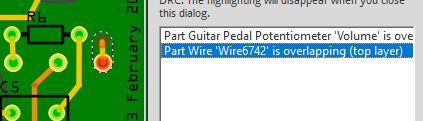
This was a fairly easy one. There is an error in your custom pot part which is causing the DRC error (there are actually a number of problems in the part.) Correcting the error fixes DRC (thankfully!)

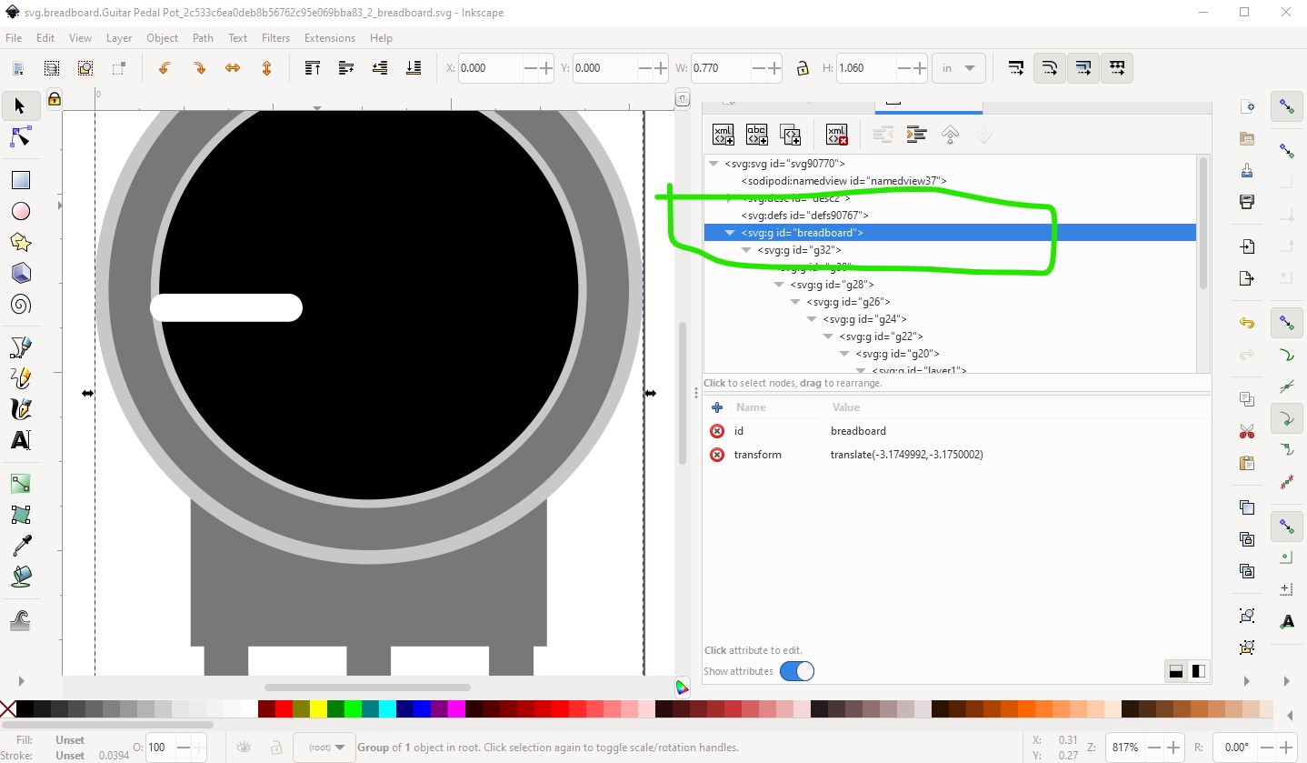
First layerIds are missing in breadboard and schematic. The only problem I know this causes is the part won’t export as an image. It is easy to fix just add an appropriate layerId to the top group like this:

same in schematic

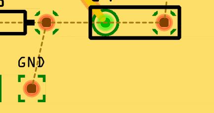
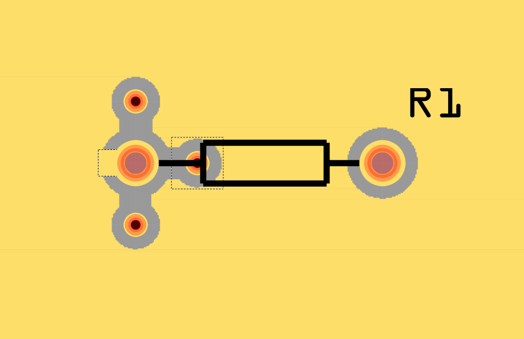
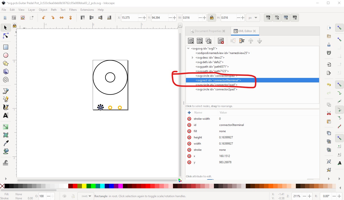
the problem here is in the pcb svg though, there is a terminalId on the pad causing the DRC error

removing this from the svg and the .fzp file fixes the issue.

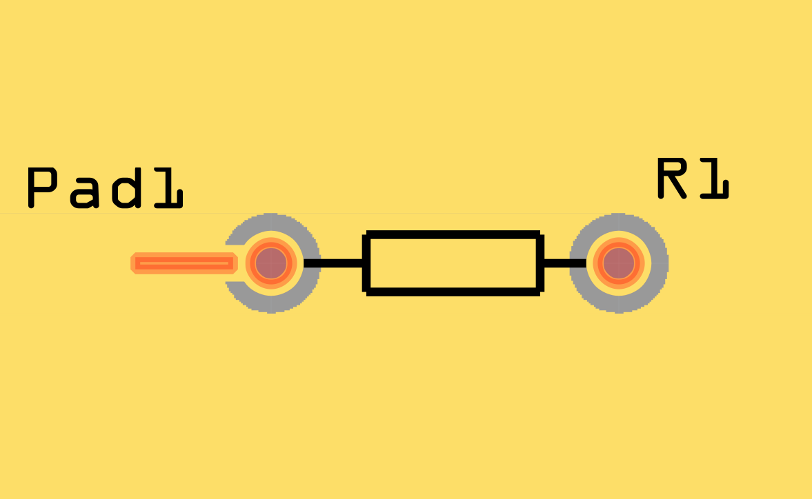
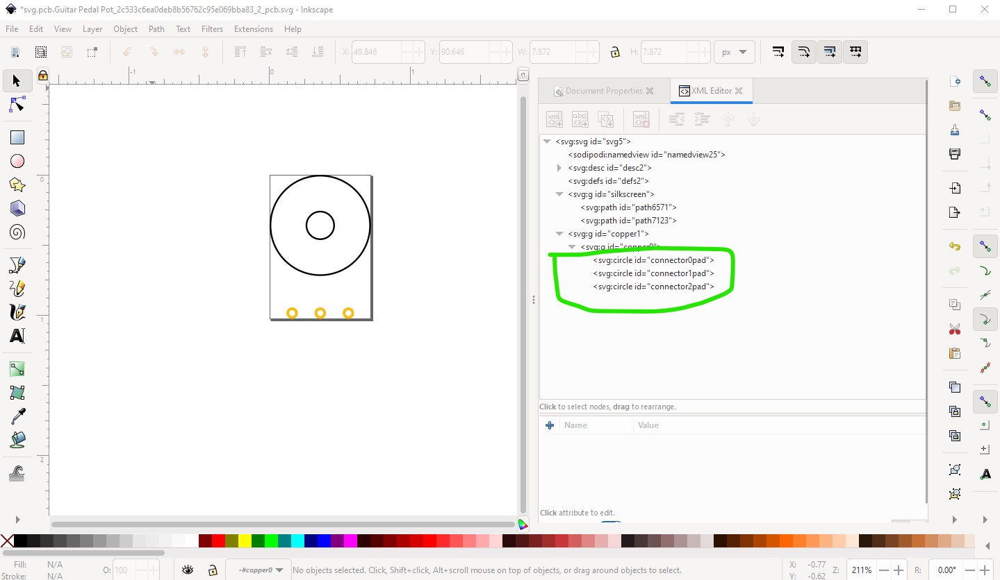
I also simplified and rescaled the svg but removing the terminalId is the important part. Then I updated the .fzp file to remove the terminalId from there. In the .fzp file

<connector type="male" name="1" id="connector0">
  <description>Input-GND</description>
  <views>
    <breadboardView>
      <p layer="breadboard" svgId="connector0pin"/>
    </breadboardView>
    <schematicView>
      <p layer="schematic" svgId="connector1pin" terminalId="connector1terminal"/>
    </schematicView>
    <pcbView>
      <p layer="copper0" svgId="connector0pad" terminalId="connector0terminal"/>
      <p layer="copper1" svgId="connector0pad"/>
    </pcbView>
  </views>
</connector>

needs to become

<connector type="male" name="1" id="connector0">
  <description>Input-GND</description>
  <views>
    <breadboardView>
      <p layer="breadboard" svgId="connector0pin"/>
    </breadboardView>
    <schematicView>
      <p layer="schematic" svgId="connector1pin" terminalId="connector1terminal"/>
    </schematicView>
    <pcbView>
      <p layer="copper0" svgId="connector0pad"/>
      <p layer="copper1" svgId="connector0pad"/>
    </pcbView>
  </views>
</connector>

I then changed the moduleId variant and file names to make this a new part. I see that the pin numbering in schematic is odd, but I didn’t correct it. It is preferable to have all the connector numbers match the id field (connector1 in this case) so the connector2s are incorrect but will work (because the schematic svg is changed in the same way!)

   <connector type="male" name="2" id="connector1">
      <description>Output</description>
      <views>
        <breadboardView>
          <p layer="breadboard" svgId="connector1pin"/>
        </breadboardView>
        <schematicView>
          <p layer="schematic" svgId="connector2pin" terminalId="connector2terminal"/>
        </schematicView>
        <pcbView>
          <p layer="copper0" svgId="connector1pad"/>
          <p layer="copper1" svgId="connector1pad"/>
        </pcbView>
      </views>
    </connector>

All these changes are in this part

Guitar Pedal Potentiometer-fixed.fzpz (6.6 KB)

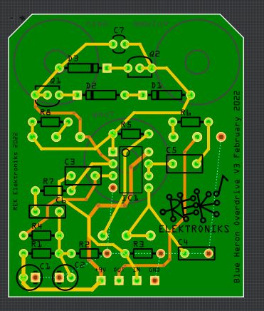
which I then substituted in to your .fzz file by doing a delete minus on the pot giving the error and replaced it with my new part. The delete minus removes the part but leaves the connections, you then need to grab the end of the connection and move it to reconnect the trace to the new part. With that done now DRC passes.

in this .fzz file (note I didn’t remake the connections in breadboard or schematic only pcb!)

BLUE_HERON_2-new.fzz (120.2 KB)

Peter

Wow! Just when I thought I was getting the hang of this custom part thing. Thanks for looking at this. I will go back and check all of my stuff.

You may want to run them through FritzingCheckPart.py which checks for errors (and flagged most of these!) This tutorial set may help as well

Peter

1 Like