I want to submit my gear motor but the problem is that in breadboard view i am not able to route the pins of the gear motor but i was able to do it in schematic view.Please help.Here is the fritzing file.
gear.fzz (8.8 KB)
Hindol
I want to submit my gear motor but the problem is that in breadboard view i am not able to route the pins of the gear motor but i was able to do it in schematic view.Please help.Here is the fritzing file.
gear.fzz (8.8 KB)
Hindol
Most of your problem is the motor you cloned from is a bendable leg part (and Parts editor doesn’t support bendable legs at present.) Running your part through my part checking script generates these two errors (among others):
Error 80: File
‘part.gear motor_d663077cedb294e0fc943e1955203998_3.fzp.bak’
At line 50
Both terminalId and legId present, only one or the other is allowed.
Error 80: File
‘part.gear motor_d663077cedb294e0fc943e1955203998_3.fzp.bak’
At line 65
This is the problem:
    <breadboardView>
      <p legId="connector0leg" layer="breadboard" terminalId="connector0terminal" svgId="connector0pin"/>
needs to be
    <breadboardView>
      <p layer="breadboard" terminalId="connector0terminal" svgId="connector0pin"/>
To make this a non bendable leg part. In this part I made that change as well as several others (listed below.) This part has a new moduleId and file names so will load along side your current part for comparison.
gear motor.fzpz (4.3 KB)
Here is a test sketch with both parts loaded.
gear-motor-fixed.fzz (14.3 KB)
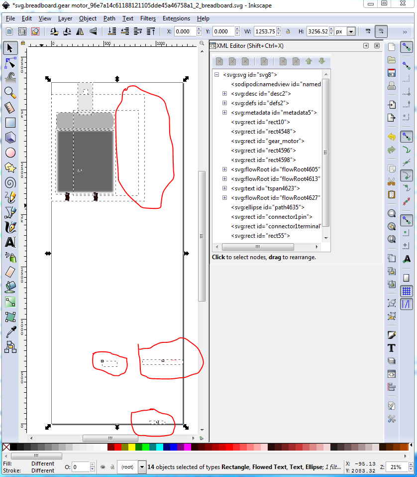
breadboard:
ungroup then delete the unneed elements (circled in red in the above image) from the svg to save space. Then rescale the svg to be the correct scale specified in the parts file document. Instructions for rescaling in Inkscape are here:
Change text font size to 1000 to make it visible.
Changed connector0 pin to be on a .1 in boundary.
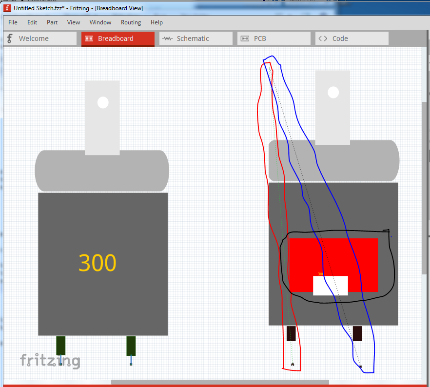
moved connector1terminal to the center bottom of connector1pin. Added connector0 terminal and placed in on the center bottom of connector0pin. I would probably remove the fuzzing of the motor rectangle as the motor isn’t likely to be fuzzy, but did not do so here. Edit->select all, resize page to drawing, group and set group id to “breadboard”, save as plain svg. Here is an image of the breadboard of both parts. As you see my new part connects correctly to the pins. Your original part has the red square (circled in black) because there is a problem with the connectorIds. The two breadboard connections connect to the top left of the part (as seen by the rats nest lines from the connections in schematic) circled in red and blue:
pcb
fine as is.
schematic
Technically mostly fine as is, but rescale to meet standards.
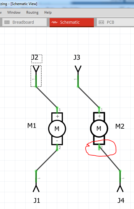
Set all stroke-widths to 10, adjust the color of the lines to match graphic standard. Change both terminalIds to be 10thou by 10thou rectangle. Move the connectors to the bottom of the xml window. Resize, regroup, save as plain svg. Note in this image of the two schematics, that your part has a path (which Fritzing won’t accept) as the connector1terminal. That is what causes the wire to connect to the center of the pin rather than the end as it should in the new part. I expect that is in the original part in core parts as well (it is circled in red in the image.)
If you haven’t seen them these tutorials may help you (they both apply to the latest version of Fritzing which most others do not):
Peter
Thanks peter  .
.
Hindol