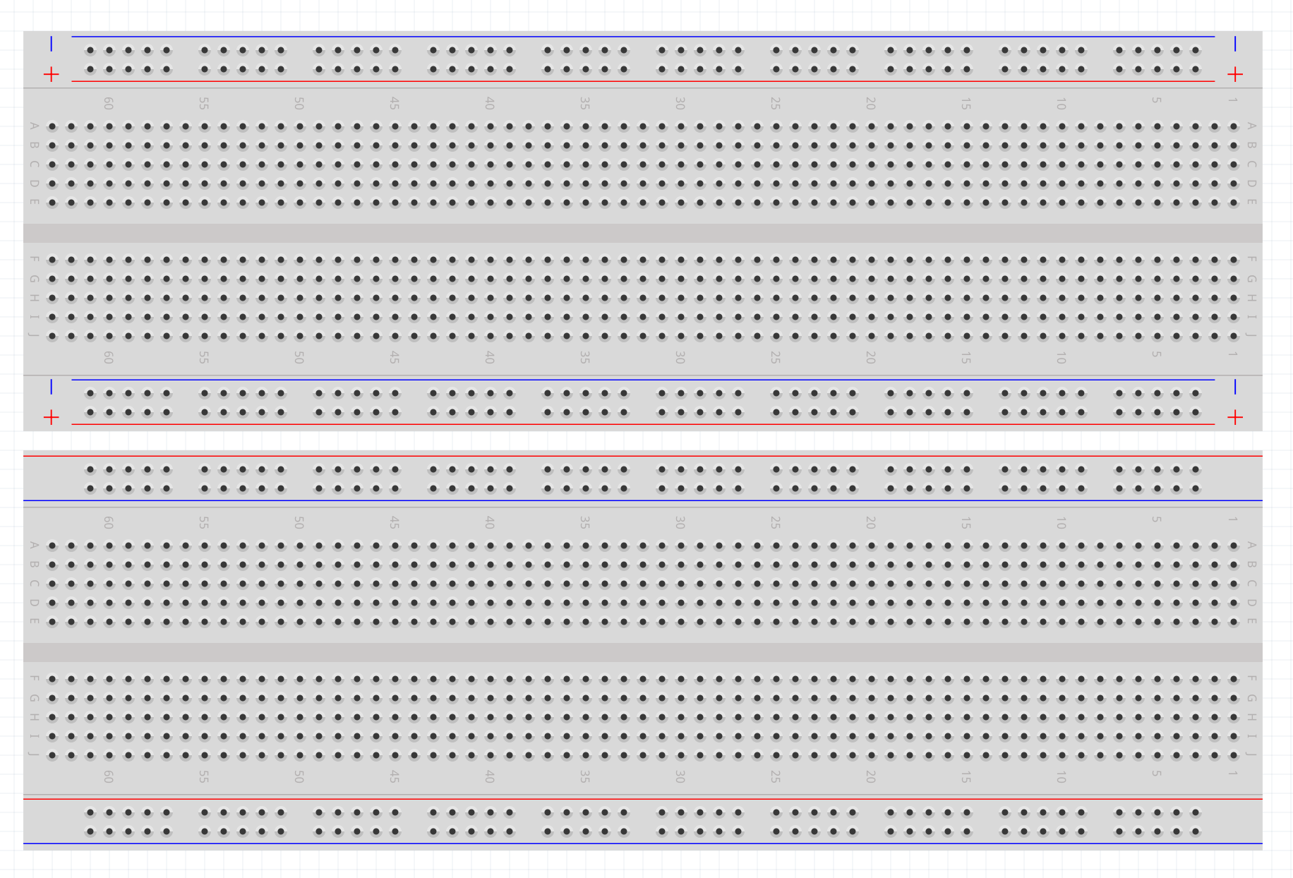
I want to document a breadboard layout for students, but some real life boards Amazon.com : 830 breadboard have the power rails marked with positive differently with respect to the a1 pin:
All the Fritzing boards with power rails displayed have the reverse, so I cant use the app for my diagrams. The color of the power rails in relation to the numbering/lettering of the rails does not reflect reality.
As far as I can see the rotate the breadboard 180 degrees works for both of the listed breadboards. Otherwise as noted above you would need a custom part (which is a fair amount of work!)
Yes, the flip works for relative positions of rails, and I don’t have time for the extra work on custom part either. I will just tell my students to ignore the row/column labels and focus on relative positions (or carefully make note of change in relative position of rails if they follow pin labels). I was just flagging for other users that common breadboards use different rail layout in case they end up at this post as I did.
Top: the new breadboard (full+ R2) Bottom: the original one (full+)
In the picture that @KjellM posted, the power rails are divided in half, while the one posted by @vanepp don’t. In the original picture from @JeremyLaurenson that part is not visible, so we can’t know…
to be entirely correct. You are right it is possible to make new breadboards somewhat easily, but there are so many different variations it is hard to keep up. This one for instance does not do for @DavidConner as his breadboards are different yet again:
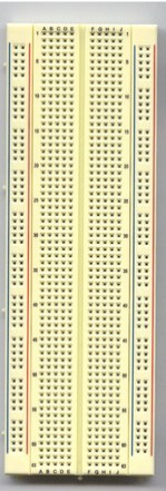
Jameco ValuePro board
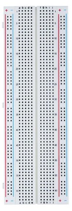
Elegoo kit board.
while it is possible to modify the breadboard to make these it is unclear it is worth the effort. I have done so for various people who needed odd size (more columns and different layouts) but it is a significant amount of work and needs to be different enough to be worth doing which I don’t think this one is.
By the way: how do you know this? through the source code? And what does this change?, because I tried the part before submitting it and seemed to work normally…
@steelgoose (who taught me most of what I know about making parts) shared it while I was making a part that included a breadboard back about 2017. There are a couple of more places (resistors and capacitors are one) where either a prepended or postpended ModuleID on the moduleId is required for correct operation. The easy way (but not always complete as one of the breadboards in core is wrong!) is look at a working part’s fzp file. For breadboards you need the ModuleID, the family to be Breadboard and the breadboard layerId to be breadboardbreadboard. For it to work correctly. As to what it affects, the only thing I know of is it allows the breadboard to rotate 45 degrees, which the standard breadboards don’t, although there may also be other things that are affected. You would need to check the source code to figure out if there are more, which is not the easiest task in the world .
To piggyback on this discussion, I’m developing some STEM Ed courses with lots of Fritzing diagrams. Like the OP, I need plus/minus signs on the power buses.
The custom breadboard provided by @roboteach in this post is exactly that, but we use half-size breadboards.
I have tried my best but cannot figure out how to edit breadboards; it’s just a change to the SVG, I know, but apparently breadboards are a special case.
Most of the reason it is somewhat complex is that most of the breadboards are dimensioned in px which with modern svg editors makes the scale wrong. I happen to have a scale corrected half breadboard around and can thus easily make a new one which I will post in a bit.
edit:
This part should do what you want. Added the + and - signs, and darkened the lettering to match the graphics standards.
No need to reciprocate, I’m happily retired and enjoy making parts (probably because unlike development I can make parts successfully .) In this case I have a rescaled version of the half breadboard (which was a bunch of work!) so the new part was maybe 15 minutes of editing both the svg and the fzp file to make a new part. I have done a bunch of breadboards for folks and am familiar with what needs to be done to make a correct breadboard so for me this is easy, for someone else probably not so easy. As I said most of the breadboards in core parts are dimensioned in px at 72DPI (Inkscape is currently 96DPI) and thus the svgs come out scaled wrong when edited with Inkscape. To add insult to injury the connectors are all groups (rather than drawing elements) and to rescale a svg you need to remove all the groups. There are a couple of hundred connectors in a breadboard (as I recall I used a python script rather than manual editing to rename the connectors on the breadboard.)
Well, this breadboard is so much improved, it should really be part of the standard core components, don’t you think? I’m not wise in the ways of Fritzing, but those two small changes make a world of difference. Not sure how to up-vote these things…
You even guessed my unexpressed wish for darker row/column markings. It really helps.
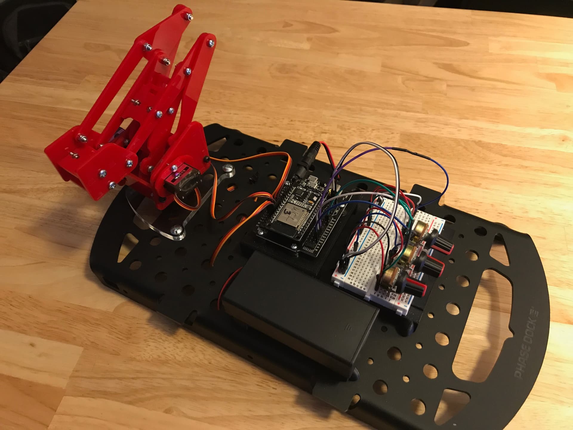
A quick shot of one of our desktop robotics projects for the kids, below. Derived from the venerable MeArm. This one controlled by pots. So many projects; so little time…
Thank you!
C
PS–no, I promise we won’t ask for a Fritzing component of a 3DOF robot arm…
Actually yes, which is why I have one. I’ve been working slowly on a clean up of core parts for a while. The problem is likely to be convincing Kjell that it is a good idea. I’ would be suggesting making changes to the breadboards which is central to most all sketches in Fritzing. While my changes are an improvement, if something turns out to be wrong it will break a lot of things so if it was my decision, I too would error on the side of “it works as is so lets leave it alone.” I don’t think there has been any modification to any of the breadboards in at least the 7 years I have been involved with Fritzing and probably a lot longer than that (probably for exactly this reason, it isn’t broken don’t try and fix it and maybe break something!)
It wouldn’t be that difficult to make one if you want one. Breadboard would be a little exciting graphically but not all that bad. The connectors for the servos are standard. See this tutorial for a for instance (not quite as complex but same general idea)
Cleaning the core parts would be great. You can do it safely if you just make new parts, move the old ones to the obsolete folder and replace the part in the core bin with the new one. Thus, old breadboards in preexisting sketches are not replaced automatically, but new sketches will be using the new parts. This is what we did with the potentiometer parts. Of course, double checking with @KjellM is better to speed up the process. Also, pull request are easier to review if they are small. Thus, it is better to create different pull requests for each part. Ask if you need help with git.
I couldn’t find this part anywhere online. Did someone perhaps created this before and be so kind to point me to a download? I’m now “cheating” by using two half+ breadboard parts, but doesn’t feel right and I end up with “ugly” no-straight lines:
It would be awesome if I could have “my” custom breadboard with the bus ports lined up exactly with the inside ports. I use fritzing only to create these kinds of images. I don’t use the Schematic, PCB or Code tabs


