1:17 Searching for parts
I’ve made this SVG in Inkscape to learn it a bit. but I’m not skilled enough to make this a functioning Fritzing part. Can anybody take over from here?

Yep. You have it mostly, this set of tutorials should get you the rest of the way.
I created schematic with this Inkscape plugin
which creates this part:
edit: Added a silkscreen of the board layout and mounting holes. Note as usual if you want mounting holes drilled, you need to drag a hole object from core parts in to the sketch and size it to match the hole you want. By default no holes will be drilled. There are no connectors in pcb as the board connections are screw terminals. Drag a header connector (single pin or 3 pin ) to the position of your choice in the sketch to give connecting points for wires from the screw terminals if you wish to connect them to the board.
edit2: Replaced breadboard with an improved version, if you have previously downloaded this part please download it again to get the new version.
1-chan-5v-relay-module.fzpz (16.9 KB)
Peter
2 Likes
That’s great!
I’ve worked through several instructions but the conversion to a usable part in Fritzing still was a bit overwelming for me.  I’ll learn sometime.
In the meantime I can help with creating some drawings.
Maybe somebody else can make it fully functional? 
It is fully functional now. Because the terminals are screw terminals you can’t really connect it to a pcb except with wires. If you need to do that, I can easily enough add pads on PCB that you can connect wires to.
Peter
Typically the pcb view would use a separate header part to connect the wires to. Or individual pad parts. No pcb pads or holes needed for the module itself. That way, it remains flexible, so different types, sizes, layouts of connectors can used with the single module part.
Took the middle path and added a silkscreen with the board outline and mounting holes (but no connectors.) Drag in a header connector to attach wires to if desired. Note the mounting holes are not drilled you need to drag a hole from core parts in the the sketch over the holes in the silkscreen to actually drill the holes.
Peter
This is great! Many Kodo’s!. Is the link/file the same as in the first message?
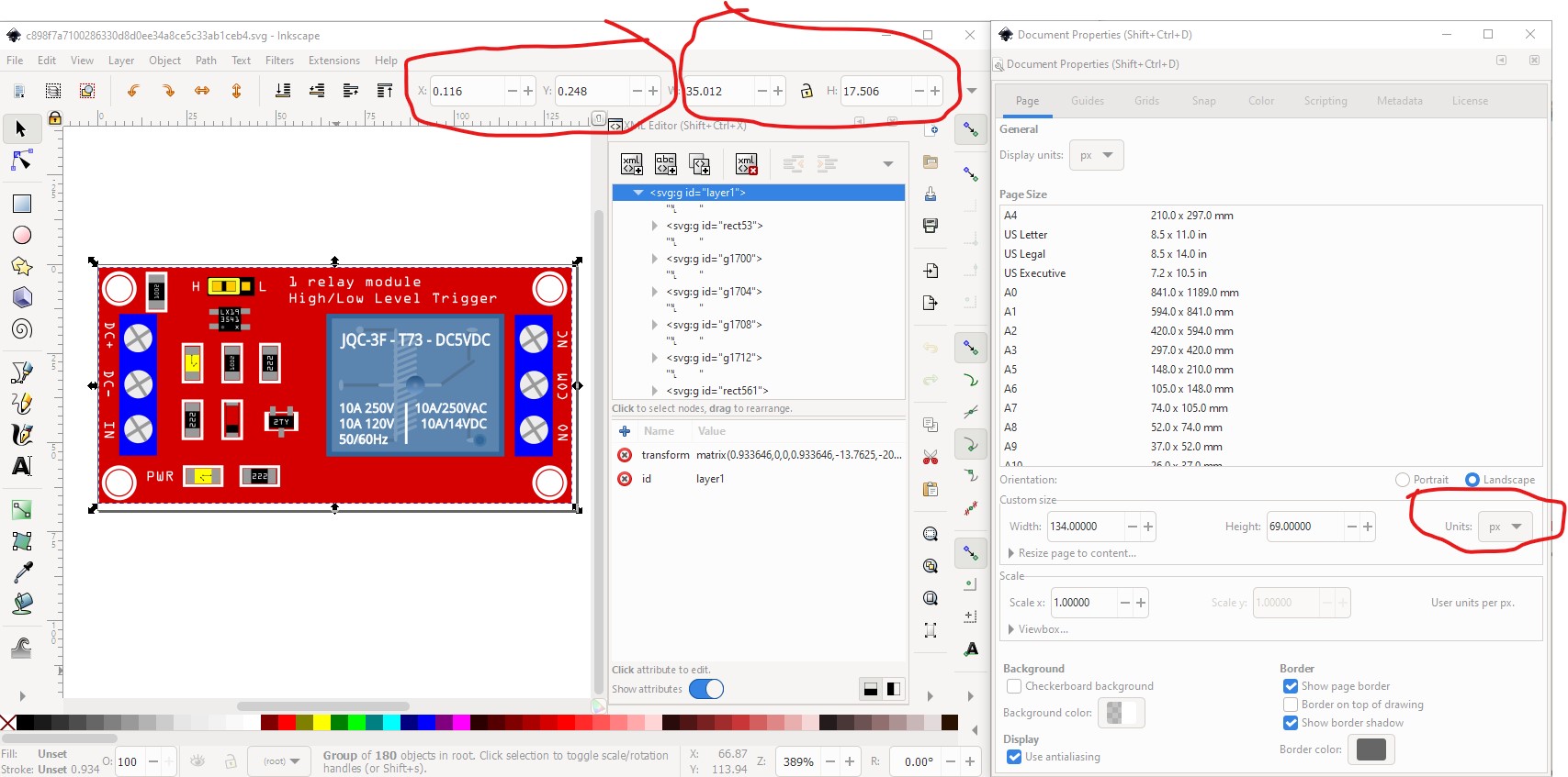
I’ve tweaked the SVG file further, drilled the holes and added the standard font types and some detail, is it a great effort to change this? Then it’s complete for use worldwide…

It is easy enough to update the breadboard svg, but the new svg is set to px (as opposed to in or mm, your original was in mm and thus probably correct) and thus is sized wrong, possibly because your svg editor is using a different DPI than 96 which Inkscape is using. Because the units are set to px Inkscape is assuming a px is 96DPI (Fritzing will guess between 72DPI and 90DPI making the scale in Fritzing wrong) and may be scaling wrong. That is easy enough for me to rescale. Also the drawing isn’t starting at 0 0 which Fritzing prefers, but most importantly the size of the board is (presumably!) wrong at 3517mm rather than the 5025mm of the original (and the dimensions of this board on web sites.)
Here is a screen shot of the part breadboard.svg with (I think!) the correct dimensions and settings:
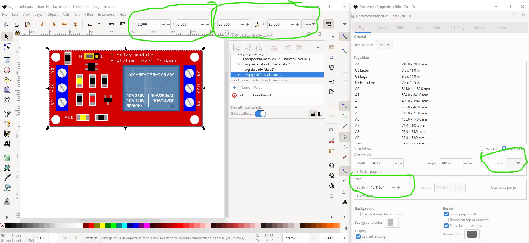
I’ll convert your svg and replace the breadboard svg with it and replace the part again (and yes, I replaced the part in the original post so there aren’t many copies some of them incorrect in the post!) As well I have learned something else FritzingCheckPart needs to be checking for. I didn’t know you could have multiple font-family entries and I don’t know what Fritzing will do with it. It is supposed to substitute fonts to one of OCRA or ‘Droid Sans’, but in practice doesn’t do that at all except in parts editor and parts editor appears to get it wrong sometimes, so having the correct fonts is important.
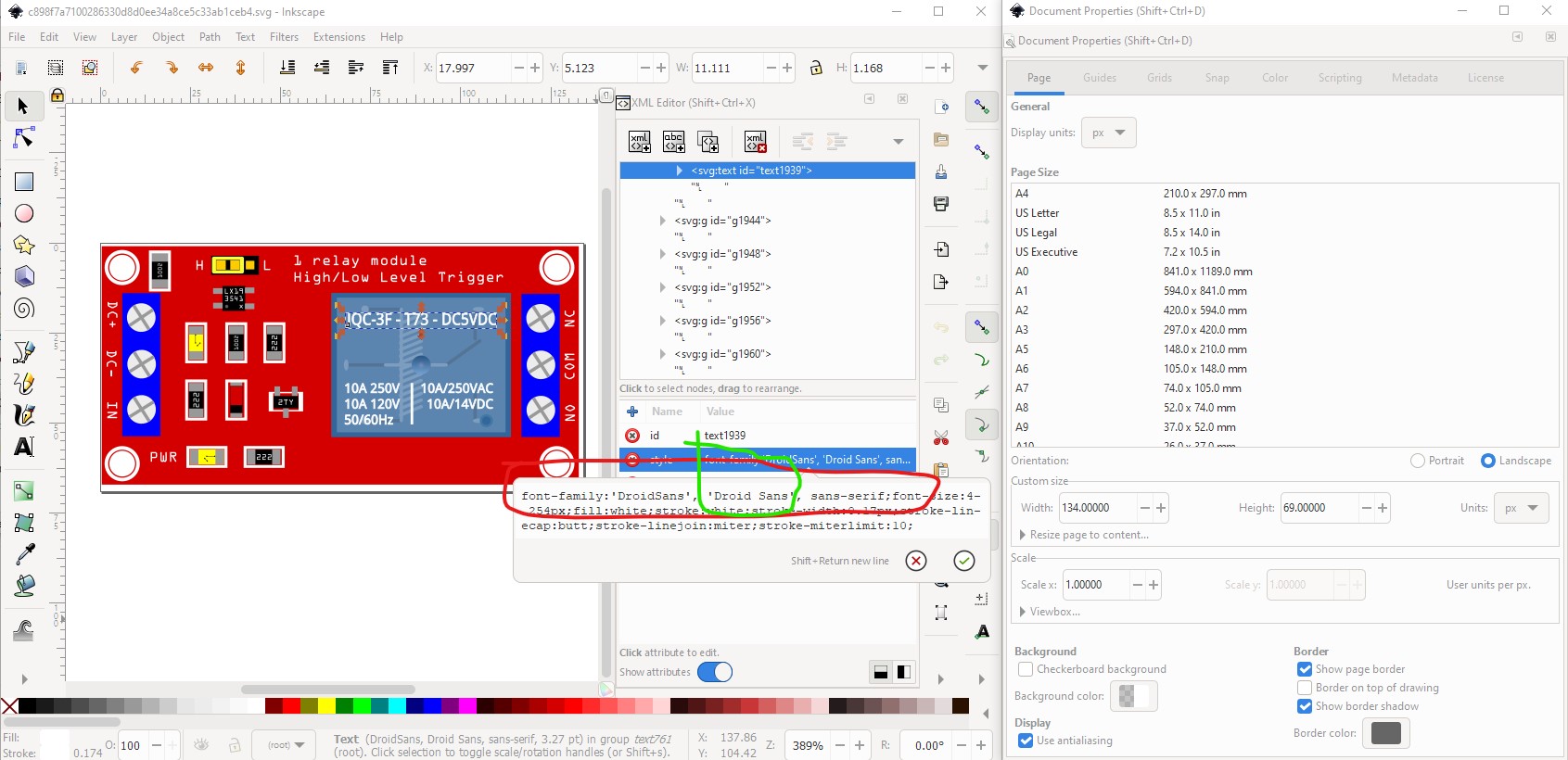
here we see three font family choices and I am not sure what Fritzing will do with this.
Peter
Well that was interesting. Something (I haven’t yet determined what) went wrong in the translation which produced this in Fritzing (where the breadboard svg renders correctly in Inkscape!):
as opposed to this;
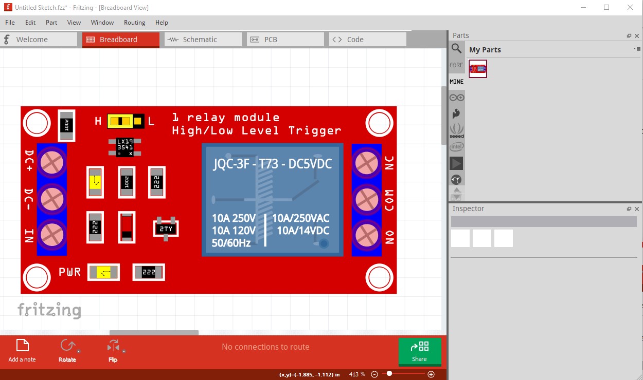
which is breadboard for the part I just replaced. Redoing the steps one at a time and saving the svgs at each step produced a working part which has been substituted in the original post, If you download the part again and delete the current part, then reload the new one you will get the new breadboard.I’ll poke at the files further to try and figure out what went wrong. If I can figure it out, FritzingCheckPart may be able to detect it and complain at an earlier stage.
Peter
Hi Peter,
Thanks for the effort you’ve put in! 
Maybe there is an direction of the problem source.
I’ve drawed the final SVG in affinity designer (much easier to draw and edit), then saved it as an flattened SVG. That did not show up correctly here on the forum.
So then I saved it in designer as a normal SVG and imported it in Inkscape. From there I exported it as a regular SVG. Maybe in one of these steps the file has changed?
Also I read now your comments about mm’s and dpi settings, I’ll remember that next time! (I saved it in 72 DPI). And I’ll do better at getting the correct size of the board.
It’s kind of a learning curve to start in electronics but it’s fun sofar.
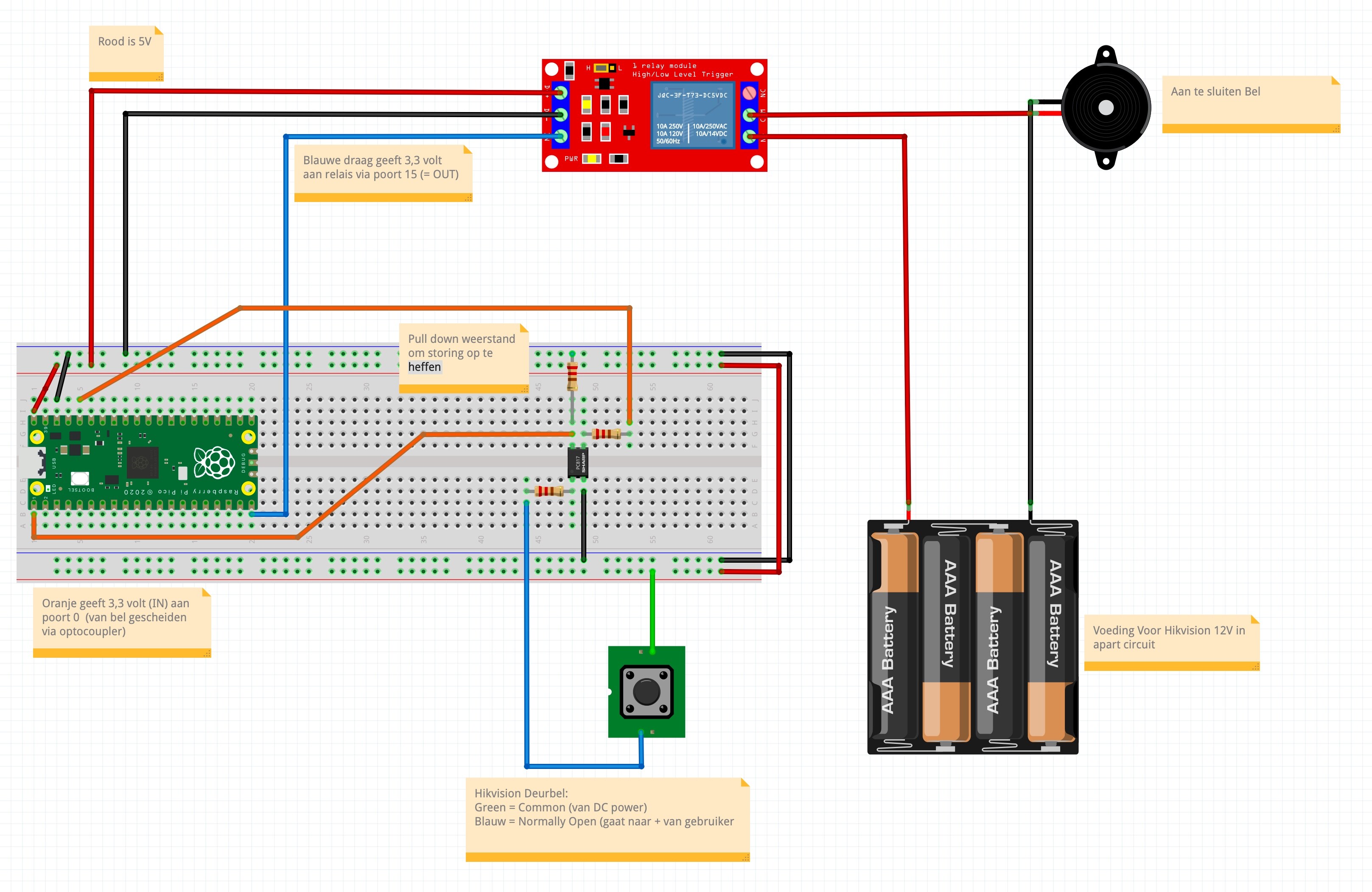
The purpose of the relay is that I have an hikvision doorbell with camera (represented by the push button in the drawing), When the button is pressed I wanted to be able to let any bell ring (represented by the buzzer in the drawing). That works now thanks to an optocoupler in the design. Before adding that it was very sensitive to small signals.
The circuitpython code:
“”"
Button and LED example for Pico. Turns on LED when button is pressed.
REQUIRED HARDWARE:
- Button switch on pin GP0.
- LED on pin GP15.
“”"
import board
import time
import digitalio
led = digitalio.DigitalInOut(board.GP15)
led.direction = digitalio.Direction.OUTPUT
button = digitalio.DigitalInOut(board.GP0)
button.switch_to_input(pull=digitalio.Pull.DOWN)
while True:
if button.value:
led.value = True
time.sleep(0.3)
led.value = False
time.sleep(0.3)
led.value = True
time.sleep(0.1)
led.value = True
time.sleep(0.3)
led.value = False
time.sleep(0.3)
led.value = True
time.sleep(0.1)
led.value = False
The forum often has troubles with svgs (even valid ones.) If it won’t load the svg you can zip it (I use 7zip which is multiplatform) and change the .zip to .fzp (which the forum will accept) and tell us that it is an svg not a real .fzp file (you have to zip it because the forum will look and see it is a svg and try to render it if you just rename the file to .fzp from .svg which used to work. )
Peter
do you happen to have 12v one?
A 12V one won’t be electrically different from this one and thus this one will do (and it wouldn’t be worth making a new part.)
Peter
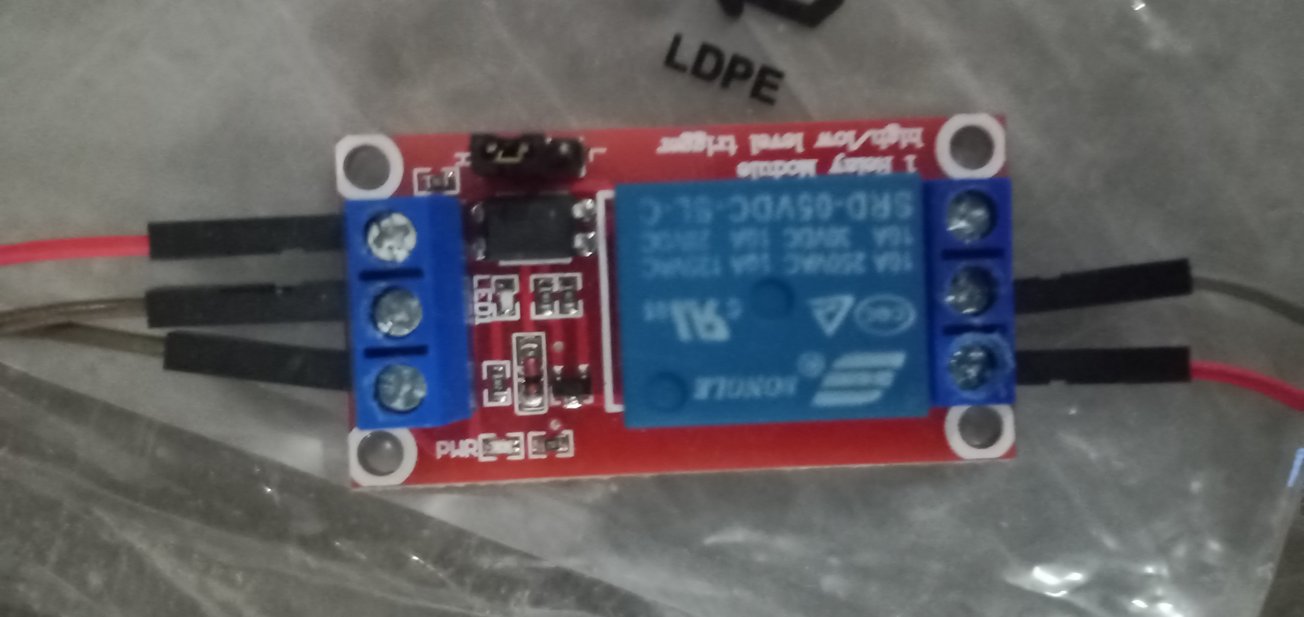
I cant find the link to download the Songle SRD-05VDC-SL-C relay, where can I find it pls, im new to fritzing
Search the forum
Yes, but there is a way around it.
Let’s say we have an SVG
![]()
Then change from

to
[svg.breadboard.Optocoupler 4N25_eb94562a32e1857bd373ee87768c627b_1_breadboard|attachment](upload://tsvEKqt5FyEI0ysO6onLCeGVPos.svg)
which will render as
svg.breadboard.Optocoupler 4N25_eb94562a32e1857bd373ee87768c627b_1_breadboard