Here it is my part design that corresponds to a two channel thyristor. This module it’s also known as a AC dimmer due to it can be used apply PWM control a led strip or any 220V AC load.
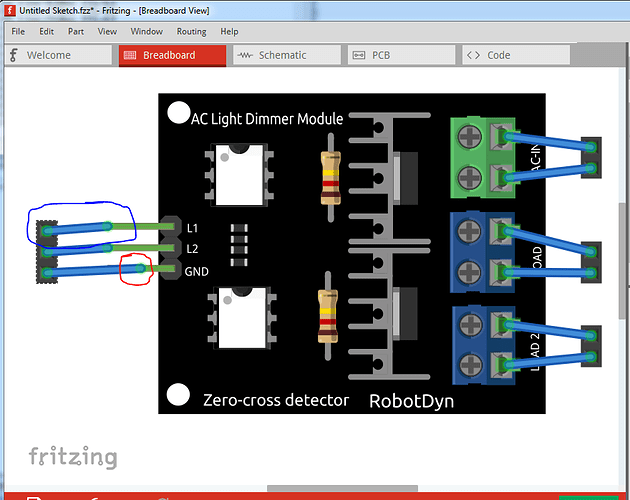
Welcome aboard! Over all a nice part, but a few issues (all easily solved). In breadboard pin 3 is missing a terminalId and thus connects to the middle of the pin rather than the end as desired (circled in red in the image) and the pins aren’t quite on .1in boundaries so the wires connect at an angle.
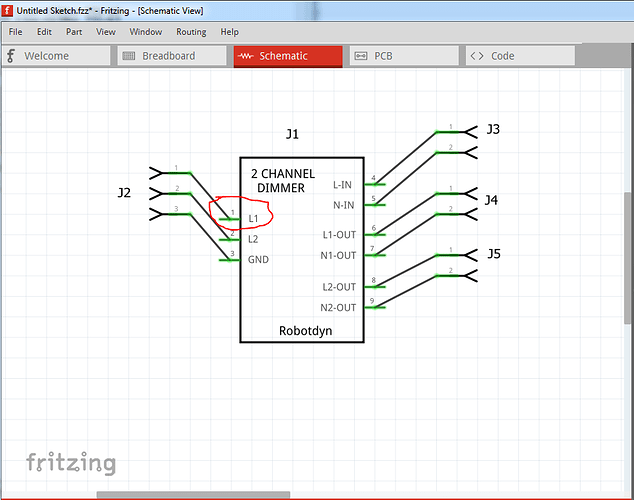
Schematic again missing terminalIds so the pins all connect in the middle of the pin:
pcb doesn’t have enough connectors which is what causes the red rectangle in the part. In this case pcb view isn’t needed (not sensible) so I chose to supress it entirely. Here is your part with all these issues fixed (you will need to delete your current part and possibly close Fritzing to make sure it is gone before it will let you load this one.)
Thyristor AC swith - 2 channel dimmer-improved.fzpz (30.7 KB)
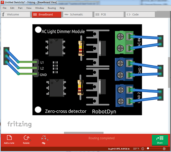
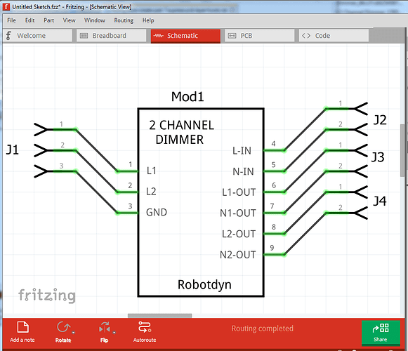
and the same three screens with this part:
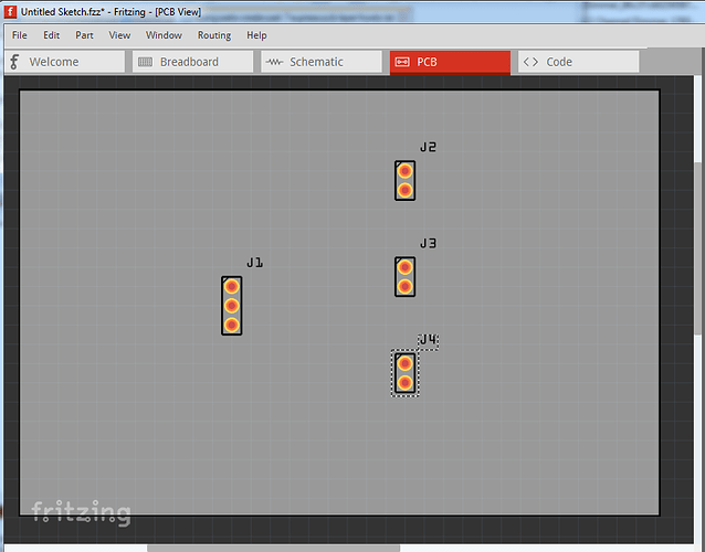
Here the headers I used to test show up in pcb but your module does not. Hope this helps, and that you make more parts  .
.
Peter
Hi! It was my very first part and I didn’t know how to design it properly. Thank you very much for your work and annotations. 
Gonzalo.
You did a great job for a first part! There wasn’t all the much wrong with it. If you haven’t seen them there are a couple of part making tutorials here in the forums:
Peter
