I’ve just crafted a new component by tweaking the existing one from this discussion. Surprisingly, it was simpler than anticipated. My approach involved crafting an SVG file for the breadboard, importing it, linking the terminals to the pre-existing pins, and updating the part number in the schematic’s SVG text.

DC_DC_SZBK07.fzpz (18.8 KB)
As with most part creation it didn’t work as intended. You would be better to start from the part here which is closer to what you want.
Your part is wrong in schematic (it is incorrect in scale and alignment)
and should have pcb suppressed as the referenced part does. This tutorial may help
Peter
1 Like
Thank you, Peter. Your assistance is greatly valued.
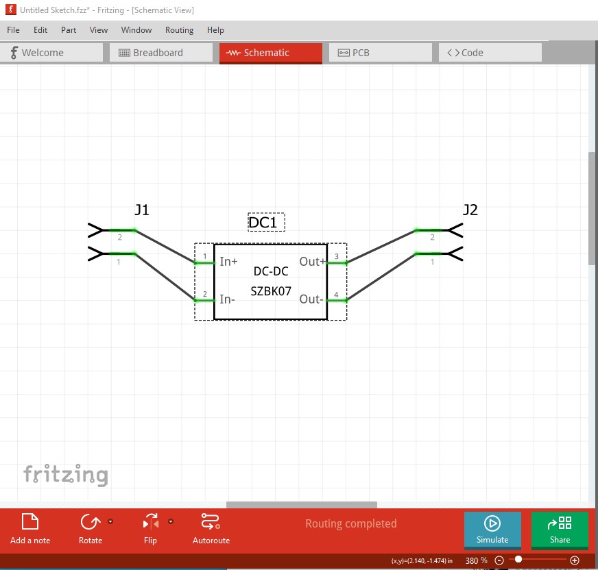
Hopefully this part has the modifications you suggested. The schematic seems to be aligned to the grid now and with the right scale, also de PCB view has all four pins marked as hybrid in the <views> section like so:
  <connector id="connector3" name="Pin 4" type="male">
   <description>OUT+</description>
   <views>
    <breadboardView>
     <p layer="breadboard" svgId="connector3pin" terminalId="connector3terminal"/>
    </breadboardView>
    <schematicView>
     <p layer="schematic" svgId="connector3pin" terminalId="connector3terminal"/>
    </schematicView>
    <pcbView>
     <p hybrid="yes" layer="copper0" svgId="connector3pin"/>
     <p hybrid="yes" layer="copper1" svgId="connector3pin"/>
    </pcbView>
   </views>
  </connector>
300w dc-dc step down converter.fzpz (25.7 KB)
Yep that works. You don’t actually need hybrid as pcb looks to be suppressed by reusing breadboard but it also won’t hurt anything.
Peter
1 Like